Use this option to define a bent bar of a selected profile.
To begin defining a bent profile, open the Bent profile dialog from:
- Menu: Steel > Bent profiles
- Ribbon: ASD - Model > Elements > Bent profiles
- Toolbar: General > Bent profiles

- Command line: RBCS_BENT.
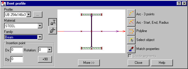
The Bent profile dialog has 3 main parts:
- On the left, you can specify basic information for the profile of a defined bar:
- Profile - select a profile of a defined bar (the most recently defined bar profile displays). Click the (…) button to open the Profile listdialog, where profiles from the databases accessible in the software may be added to the list of available profiles.
- Material - select the type of material assigned to a defined bar
- Family - select a bar family (group), to which a defined bar will be assigned
- Insertion point - define coordinates of the bar offset (Dx and Dy), and the rotation of the bar profile about the bar longitudinal axis (select a value from the list or enter a value in the Rotation field). The offset denotes translation of the profile center with respect to the insertion line.
- In the middle is a graphical field that displays a selected profile of a defined bar positioned in relation to the insertion line (under the graphical field, characteristic distances of the profile fibers from the profile axis are displayed). You can define offsets graphically, by using the cursor to translate a profile with respect to the axis or by specifying characteristic points of a profile.
Under the schematic drawing, there is the More >> (or Less <<) button, which opens (closes) an additional field where you can specify:
- a surface finishing type for a profile (for example, hot-dip galvanized, electrogalvanized, anticorrosive paint, fireproof coat). A default type of surface finishing can be selected in the Project preferences dialog on the Materials tab; this dialog also allows adding a new surface finishing type or deleting a selected type from the list of available surface finishing types.
- profile properties (area, moments of inertia, and so on) - see the description of the Profile list dialog. After you right-click in this field, the context menu displays:
- Select All - selects the contents of the edit field
- Copy - copies the contents of the edit field to the Clipboard
- Paste - pastes the Clipboard contents to the edit field
The following icons are also available in this part of the dialog:
![]() - blocks the position of axes in the graphical field and lets you translate a profile
- blocks the position of axes in the graphical field and lets you translate a profile
![]() - blocks the position of a profile in the graphical field and lets you translate profile axes
- blocks the position of a profile in the graphical field and lets you translate profile axes
- Use the icons on the right to define the bar insertion:
 - 3 arc points
  - arc: start, end, and radius
  - polyline
  - select object
  Match properties - used to adopt (inherit) parameters from a defined bar profile.
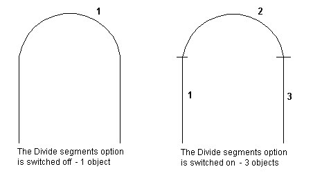
Below the icons is the Divide segments option - if this is not selected, a bent profile is defined as one object (despite that it may consist of several elements, such as a polyline composed of arc, segment, and arc). If this is selected, the bent profile is divided into separate objects when the type of profile parts changes (a polyline composed of arc, segment, and arc is divided into 3 separate parts: 2 arcs and a segment). The drawing below illustrates schematically how this option works.
When the Bent profile dialog displays, it displays parameters of the most recently defined bar profile.