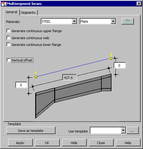
You can define a multisegment plate girder (beam) in the 3D space.
To begin defining a plate girder, open the Multisegment beam dialog from:
- Menu: Steel > Plate girders > Multisegment beam
- Ribbon: ASD - Model > Elements > Multisegment beam
- Toolbar: Plate girders > Multisegment beam
 .
.
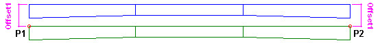
In the drawing area, click to specify the beginning and end of the beam (P1 and P2).
Define the plane in which the web of a multisegment beam will be positioned:
- Points P1, P2, and an additional user-defined point determine the web plane
- In the local coordinate system, according to the Z axis
Specify the number of segments (from 1-5) of the multisegment beam.
Characteristic points of a beam (P1 and P2) define the location of a multisegment beam in 3D space (see the drawing below that shows a beam composed of 3 segments):
- Point 1 is the beginning point of a multisegment plate girder (the first point defined in the drawing). It determines the position of a point in the middle of the flange width on the top face of the upper flange of the beam (the beginning of the first beam segment).
- Point 2 is the end point of a multisegment plate girder (the second point defined in the drawing). It determines the position of a point in the middle of the flange width on the top face of the upper flange of the beam (the end of the last beam segment).
The beam web is always located on the plane parallel to the Z axis of the current UCS.

The total length of a multisegment beam is evaluated on the plane that is defined by points P1 and P2 and denotes length of the segment connecting these points.
|
Upper flanges fitted to the upper plane  |
Upper flanges fitted to the lower plane 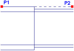 |
For points P1 and P2, it is also possible to define vertical offsets. A positive offset value moves the point up, while a negative value moves the point down.
Define offsets:
- If Vertical offset is not selected
Offsets can be defined separately for the beginning point (P1) and the end point (P2) of a beam. If the offset value at point P1 differs from the offset at point P2, the geometry of a multisegment beam changes. The total length of a a multisegment beam and lengths of individual segments displayed on the Segments tab will be recalculated, and current values of the total beam length and lengths of individual segments (lengths of all segments will be identical) will display.
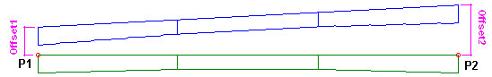
- If Vertical offset is selected
The same offset at both beam ends is defined, and the beam is shifted up or down (depending on the offset sign) by the same value at each point along the beam length. The total length of a multisegment beam and lengths of individual segments displayed on the Segments tab do not change.
A multisegment beam consists of several segments, each of which is made from 3 plates (web, upper flange, and lower flange) joined by workshop welds.
Components of a segment are connected by means of fillet welds with a user-defined thickness. Individual beam segments are joined with each other by means of butt welds with a user-defined thickness.
Specify parameters :
- Materials
- Family of elements - families of parts available on the selection list are those defined in the Family Manager dialog. To add a family to the list, click
 . The Family manager dialog displays, where you can select a family.
 - Generate continuous upper flange
If this is selected, the upper flange will be defined as 1 plate along the entire beam length.
If this is not selected, the upper flange will be defined as separate plates for each segment of a multisegment beam. These plates are connected by welds in places of contact of successive segments of a multisegment beam.
- Generate continuous web
If this is selected, the web will be defined as 1 plate along the entire beam length
If this is not selected, the web will be defined as separate plates for each segment of a multisegment beam. These plates are connected by welds in places of contact of successive segments of a multisegment beam.
- Generate continuous lower flange
If this is selected, the lower flange will be defined as 1 plate along the entire beam length
If this is not selected, the lower flange will be defined as separate plates for each segment of a multisegment beam. These plates are connected by welds in places of contact of successive segments of a multisegment beam.
At the bottom of the dialog is the Use template selection field, which contains user-defined templates (schemes) of plate girders (multisegment beams). After you define plate girder geometry, you can save the settings by typing a name in the Use template field and clicking Save as template. In the future, after you begin to define a plate girder (multisegment beam), you can select the name of a saved template so that all its parameters will be applied to the new plate girder.
Use the buttons at the bottom of the dialog:
- Apply - after you click this, the plate girder defined in the dialog is generated on the screen without closing the dialog. This lets you check whether the plate girder has been generated correctly.
- OK - click this to generate the defined plate girder and close the dialog.
- Hide - after you click this, the dialog is no longer visible on the screen. To restore the dialog display on the screen, press Esc.
- Close - click this to close the dialog without generating the plate girder.
After you finish defining basic parameters of a multisegment plate girder, click the Segments tab to display the Multisegment beam - Segments dialog.