The Ground Beam - Geometry option defines geometry and reinforcement of an RC ground beam. Select the option from:
- Menu: Reinforcement > Structure elements > Structure elements - reinforcement > Ground beam
- Ribbon: ASD - Structure elements > Structure elements - reinforcement > Ground beam
- Toolbar: Structure elements - reinforcement > Ground beam
 .
.
The following dialog displays:
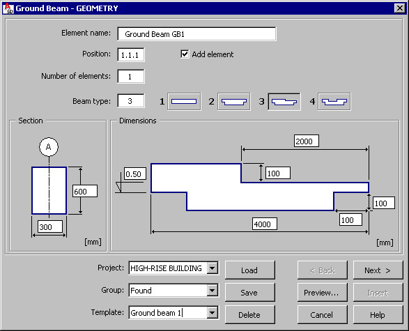
The following information is diplayed in the top part of the dialog :
- Name of an RC structure element (RC beam)
- Number of position
- Number of defined elements (beams) - this number has an effect on the steel table
- Ground beam type; the following types of a ground beam are available (the number is entered into the Beam type edit field) - the type refers to the shape of longitudinal section of a beam (the cross section is a rectangular section):
-

-

-

-
 .
.
-
Select the Add element option to group the reinforcing bars (or reinforcing wire fabrics) of the ground beam reinforcement into an element while generating the formwork / reinforcement of the ground beam. The name specified in the Element name field is added on the Model tab of the Object Inspector dialog. The element (the group of reinforcing bars) displays in the Element manager dialog.
Once ground beam geometry is selected, define the dimension values of beam cross-section and longitudinal section; a schematic drawing of beam sections is presented in the lower part of the dialog. A number of dimensions defined for a longitudinal section depends on a selected ground beam type.
You can add a description of structural axes (by standard, the letter A is entered for the cross-section) and the reference level in a schematic drawing of a ground beam (in a cross-section and a longitudinal section); these values are editable.
After defining the ground beam dimensions and clicking Next, the Ground beam - Stirrups dialog displays.