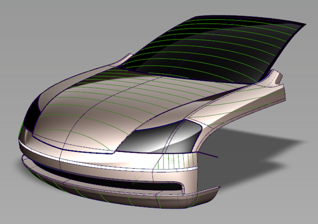
About creating visual cross section lines on the selected surfaces and meshes, using one of five different methods, with the Windows > Editors > Cross Section Editor![]() tool.
tool.
The editor lets you define groups of cross sections with specific characteristics, apply them to any geometry at any time, and even save them with your model.
You can also convert the visual cross-sections to section data geometry (using Tools > Promote in the Cross Section Editor).
To obtain NURBS curves, you must use the Curve Edit > Fit Curve![]() tool on the section data.
tool on the section data.
Types of cross-sections
- Axis Increment
-
Cross sections are created in the X,Y or Z planes with a regular step size starting from the origin. For example, with a step size of 2.5 cm, the cross section specs are created at -2.5, 0.0, 2.5, 5.0... and so on.
When the Auto Range option is turned on (default), the cross sections are shown over the entire surface. Otherwise, you must explicitly set the range over which the cross sections should be displayed.
- Axis Discrete
-
Cross-sections are individually created in a plane perpendicular to the X, Y or Z axis at a specific location. That X, Y or Z location is specified through the control window or by clicking the mouse in the view.
- Picked Reference
-
Cross sections are created at the intersection between the geometry and selected section data or construction planes.
Note:Section data can be created from degree 1 NURBS by using the crvToSection plug-in.
- Planar
-
Cross-sections are created at the intersection between the geometry and a (temporary) construction plane generated on the fly. You can also select an existing construction plane.
- Radial
-
Cross-sections are created based on a driving curve you specify, and the Number of planes option. Points, equally spaced by arc length, are placed on the curve to correspond to the number of sections. A plane is then defined perpendicular to the curve’s tangent at each of these points. The cross-sections are created where the planes intersect the geometry.
The driving curve can be a free curve, a curve-on-surface, or a surface edge or isoparm.
You can control the accuracy of visual cross sections by setting the Tessellator option in the diagnostic Shading section of the Control Panel. The Accurate setting will produce more accurate cross sections.
Cross section display
- Visual cross-sections on surfaces have a different active and inactive color than visual cross-sections on meshes.
- Visual cross-sections on objects that belong to a Pickable layer with an assigned color inherit that color, whether the objects are surfaces or meshes.
- Visual cross-sections are also visible on Reference and Inactive layers, and their color matches the color defined for those states.
- Wireframe anti-aliasing applies to visual cross sections. Turn anti-aliasing on and off through WindowDisplay > Anti-Alias > Wireframe Anti-Alias.)
- When you toggle on a construction plane (Construction > Toggle Construction Plane
 ), Axis Increment (X, Y, Z) sections are re-drawn to match the new coordinate system. Other section types (discrete, planar, radial) maintain their original location.