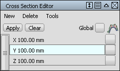
Create Axis Increment (X, Y, Z) cross sections
- Choose Windows > Editors > Cross Section Editor
 .
. - Do one of the following:
- Select the surfaces and meshes to which you want to apply the cross-sections. (Make sure that the Global checkbox is unchecked.)
- To apply the cross sections to ALL surfaces and meshes, check the Global checkbox.
Note:If Global is turned off and nothing is selected, you can still create cross section groups and apply them later.
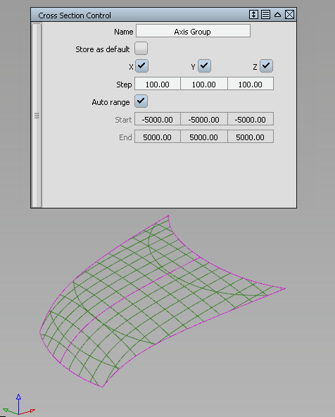
- In the editor, choose Axis Increment from the New menu.
Selected surfaces/meshes turn purple. The control window opens.
Cross sections appear on the geometry.
A new section group called Axis Group appears in the editor.
- In the control window:
- Click in the Name text field, and type in a new name. Hit
 (Windows) or
  (Mac).
 The new name for the cross section group is displayed in the Cross Section Editor.
- Check on Store as default if you want the cross section group to become a new default (like the preset X, Y, and Z groups). It can then be applied to objects in other stages.
The default group remains in the Cross Section Editor even after you exit and re-launch Alias. To delete it, you must select it and choose Delete > Selected in the editor’s menu.
- Change other option settings if desired (for example, the Step).
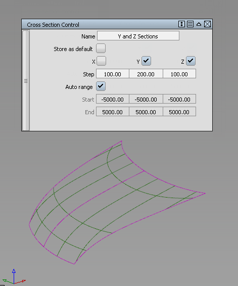
The cross sections update.
See Windows > Editors > Cross Section Editor for option details.
- Click in the Name text field, and type in a new name. Hit
Create Axis Discrete cross sections
- Choose Windows > Editors > Cross Section Editor.
- Do one of the following:
- Select the surfaces and meshes to which you want to apply the cross-sections. (Make sure that the Global checkbox is unchecked.)
- To apply the cross sections to ALL surfaces and meshes, check the Global checkbox.
Note:If Global is turned off and nothing is selected, you can still create cross section groups and apply them later.
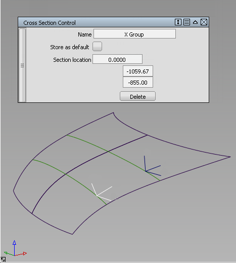
- In the editor, choose Axis Discrete > Axis Discrete X (Y or Z) from the New menu to create sections perpendicular to the X, Y or Z axis respectively.
Selected surfaces/meshes turn purple. The control window opens.
- Enter a value for Section Location (along the chosen axis) in the control window, or click on the geometry or in space in the view, to specify the X, Y, or Z location of the section.
The section and a corresponding locator appear in the view.
A new value is added to the Section Location list.
A new section group called X Group, Y Group, or Z Group appears in the editor.
- Do one of the following:
- Click on the locator and drag to move the section.
- Enter additional section locations (the values are added to the list in the control window).
- Double-click a value in the list to edit it. (If the corresponding locator is attached to a surface, it becomes a space locator after editing.)
- Select a value in the list and click the Delete button.
- In the control window:
- Click in the Name text field, and type in a new name. Hit (Windows) or (Mac).
The new name for the cross section group is displayed in the Cross Section Editor.
- Check on Store as default if you want the cross section group to become a new default (like the preset X, Y, and Z groups). It can then be applied to objects in other stages.
The default group remains in the Cross Section Editor even after you exit and re-launch Alias. To delete it, you must select it and choose Delete > Selected in the editor’s menu.
- Click in the Name text field, and type in a new name. Hit
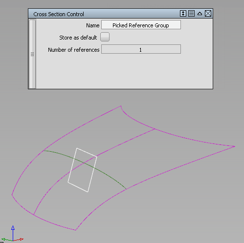
Create Picked Reference cross sections
- Choose Windows > Editors > Cross Section Editor.
- Do one of the following:
- Select the surfaces and meshes to which you want to apply the cross-sections. (Make sure that the Global checkbox is unchecked.)
- To apply the cross sections to ALL surfaces and meshes, check the Global checkbox.
Note:If Global is turned off and nothing is selected, you can still create cross section groups and apply them later.
- In the editor, choose Picked Reference from the New menu.
Selected surfaces/meshes turn purple. The control window opens.
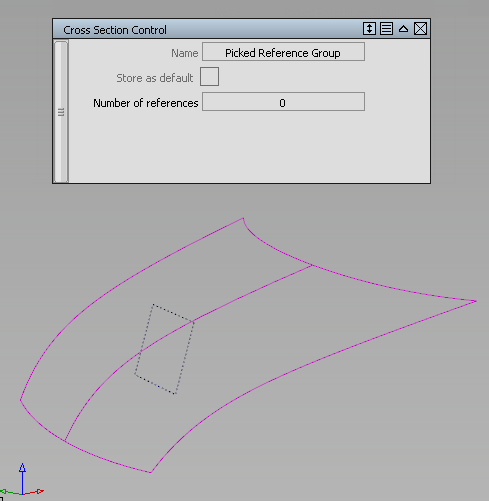
- Select the construction plane(s) and/or section data you want to use as reference.
The control window displays how many reference items have been selected.
The cross-sections appear in the view.
A new section group called Picked Reference Group appears in the editor.
- In the control window:
- Click in the Name text field, and type in a new name. Hit (Windows) or (Mac).
The new name for the cross section group is displayed in the Cross Section Editor.
- Check on Store as default if you want the cross section group to become a new default (like the preset X, Y, and Z groups). It can then be applied to objects in other stages.
The default group remains in the Cross Section Editor even after you exit and re-launch Alias. To delete it, you must select it and choose Delete > Selected in the editor’s menu.
- Click in the Name text field, and type in a new name. Hit
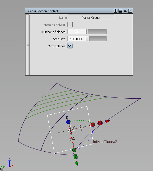
Create Planar cross sections
- Choose Windows > Editors > Cross Section Editor.
- Do one of the following:
- Select the surfaces and meshes to which you want to apply the cross-sections. (Make sure that the Global checkbox is unchecked.)
- To apply the cross sections to ALL surfaces and meshes, check the Global checkbox.
Note:If Global is turned off and nothing is selected, you can still create cross section groups and apply them later.
- In the editor, choose Planar from the New menu.
Selected surfaces/meshes turn purple. The control window opens.
- Choose the creation method for your construction plane by clicking one of the buttons at the bottom of the screen: View | Slice | 3 Pt | Geom | World. These work the same as in the Construction > Plane
 tool.
tool. - Click one, two or three points to define the plane, depending on the method you chose above.
The construction plane appears, as well as the section it cuts through the geometry.
A new section group called Planar Group appears in the editor.
- In the control window:
- Click in the Name text field, and type in a new name. Hit (Windows) or (Mac).
The new name for the cross section group is displayed in the Cross Section Editor.
- Check on Store as default if you want the cross section group to become a new default (like the preset X, Y, and Z groups). It can then be applied to objects in other stages.
The default group remains in the Cross Section Editor even after you exit and re-launch Alias. To delete it, you must select it and choose Delete > Selected in the editor’s menu.
- Change the Number of planes and Step size (spacing) if desired.
- Turn on Mirror planes if you want cross sections to be drawn on both sides of the defining plane. (For example, if Number of planes is set to 3, and Mirror planes is on, the total number of sections will be 5).
The cross sections update.
See Windows > Editors > Cross Section Editor for option details.
- Click in the Name text field, and type in a new name. Hit
- Use the plane manipulator to change the position or orientation of the plane if needed.
The cross-sections update.
Create Radial cross sections
- Choose Windows > Editors > Cross Section Editor.
- Do one of the following:
- Select the surfaces and meshes to which you want to apply the cross-sections. (Make sure that the Global checkbox is unchecked.)
- To apply the cross sections to ALL surfaces and meshes, check the Global checkbox.
Note:If Global is turned off and nothing is selected, you can still create cross section groups and apply them later.
- In the editor, choose Radial from the New menu.
Selected surfaces/meshes turn purple. The control window opens.
- Select the driving curve(s). Clicking a selected curve deselects it. Note:
If Chain selection is turned on, you can select a group of tangent continuous curves all at once.
Small planes, equally spaced by arc length, are displayed on the curve(s), corresponding to the number of sections. The planes are perpendicular to the curve’s tangent at each location. The default number of planes is 10.
Cross sections appear on the geometry, where it intersects the planes.
A new section group called Radial Group appears in the editor.
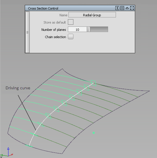
Cross sections are created perpendicular to the driving curve’s tangent, at equally spaced points.
- In the control window:
- Click in the Name text field, and type in a new name. Hit (Windows) or (Mac).
The new name for the cross section group is displayed in the Cross Section Editor.
- Check on Store as default if you want the cross section group to become a new default (like the preset X, Y, and Z groups). It can then be applied to objects in other stages.
The default group remains in the Cross Section Editor even after you exit and re-launch Alias. To delete it, you must select it and choose Delete > Selected in the editor’s menu.
- Use the Number of planes slider to adjust the number of radial sections. The minimum is 2.
- Click in the Name text field, and type in a new name. Hit
Apply cross section groups
- Select the surfaces or meshes to which you want to apply the sections.
- Click on a section group in the Cross Section Editor to select it. Hold the
 key to add to the selection or the
  key to select all the section groups within a range.
 If Global is turned on (check mark is visible and Apply button is greyed out), the selected section groups are applied to all visible surfaces and meshes. (If you import or create new geometry, or show hidden geometry, the selected section groups are applied to those as well.)
If Global is turned off (no check mark), selecting a section group only applies it to the selected surfaces and meshes.
- Select additional surfaces and meshes if needed.
If Global is turned off, click the Apply button to apply the selected cross section groups to those.
- Double-click the group’s name in the editor to open the control window from where you can change some of the options.
The cross sections update on the geometry.
See Windows > Editors > Cross Section Editor for details.
Change the visual cross section settings
- In the Cross Section Editor, click on the cross section group you want to modify.
The control window opens.
- In the control window, modify the option settings.
For the Planar type, you can also modify the construction plane.
Create and change a curvature comb on a visual cross section group
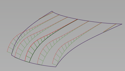
- Click the Curvature comb checkbox to the right of the goup’s name in the Cross Section Editor so that a check mark appears.
The curvature combs appear in green on the model.
- Click on the group’s name to open the control window.
A Curvature scale slider, Curvature samples slider and Lock curvature checkbox appear in the control window.
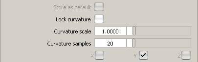
- Adjust the Curvature scale slider to scale the length of the curvature combs.
- Adjust the Curvature samples slider to change the number of quills on the combs.
- Click the Lock curvature checkbox to prevent any accidental modification of the cross sections curvature combs when using the global Comb Scale or Samples sliders from the Control Panel. (See Control Panel > Curvature
 ). Note:
Curvature combs are not available on mesh cross sections.
Hide curvature combs on existing visual cross sections
- Pick a surface on which you have created cross sections.
- Click the Curvature comb checkbox in the Cross Section Editor so that the check mark disappears.
Snap and measure to visual cross sections
The following objects will automatically snap to the visual sections when you position them by clicking a section:
- Blend points
- Point-of-interest (when tumbling)
- Construction objects (points, vectors, construction planes)
You can also snap the following objects to visual sections by holding down the ![]() and
and ![]() keys and clicking a section:
keys and clicking a section:
- Control vertices
- Edit points
- Pivot point
In addition, the following measurement tools work on visual sections:
- Show deviation from the Control Panel
- Locators > Annotate
- Locators > Measure > Distance
- Locators > Measure > Angle
- Locators > Deviation > Closest Point
- Locators > Deviation > Curve to Curve
- Locators > Deviation > Curve to Surface
Modifying surfaces with visual cross-sections causes those sections to update, in turn causing the measurement locators to update.
Clearing a visual cross-section group, or modifying its definition (through the control window) deletes the associated measurements.
The pick chooser appears when selecting overlapping visual cross-sections to create measurements.
Convert visual cross sections to section data geometry
- Select the surfaces on which you want to promote sections.
- Choose Tools > Promote
 in the Cross Section Editor window.
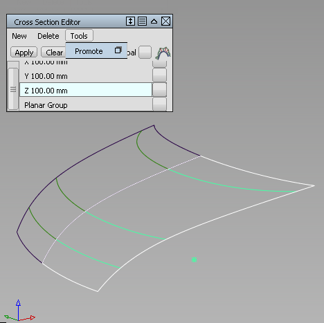
- Do one of the following:
- Select additional surfaces with applied section groups.
- Select individual sections by clicking on them.
- Click the Go button.
Section data is created for all active (highlighted) visual sections.
If Sort sections is turned on in the control window (default), X, Y, and Z sections are put in separate color-coded layers.
If Merge sections is turned on in the control window (default), cross-sections that are position (G0) continuous, and belong to the same intersecting plane, are merged into a single section curve.