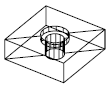
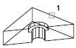
Creates new 3D solids and surfaces by slicing, or dividing, existing objects.
Access Methods
Button
 Toolbar: Modeling tool set
  Solids - Edit tool group (expanded) Slice Menu:
Modify
3D Operations
Slice
Solids - Edit tool group (expanded) Slice Menu:
Modify
3D Operations
Slice
Summary
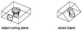
The cutting plane is defined with 2 or 3 points, by specifying a major plane of the UCS, or by selecting a surface object (but not a mesh). Either one or both sides of the sliced 3D solids can be retained.
The sliced objects retain the layer and color properties of the original solids. However, the resulting solid or surface objects do not retain a history of the original objects.
| Objects that can be sliced | Objects that can be used as cutting planes |
|---|---|
| 3D solids | Surfaces |
| Surfaces | Circles |
| Ellipses | |
| Circular or elliptical arcs | |
| 2D splines | |
| 3D polyline segments |
List of Prompts
The following prompts are displayed.
- Objects to slice
-
Specifies the 3D solid or surface object that you want to slice. If you select a mesh object, you can choose to convert it to a 3D solid or surface before completing the slice operation.
- Start point of slicing plane
-
Sets the first of two points that define the angle of the slicing plane. The slicing plane is perpendicular to the XY plane of the current UCS.
- Second point on plane. Sets the second of two points on the slicing plane.
- Planar object
-
Aligns the cutting plane with a plane that contains a selected circle, ellipse, circular or elliptical arc, 2D spline, or 2D polyline segment.
- Select a circle, ellipse, arc, 2D-spline, or 2D-polyline. Specifies the object to use for alignment.
- Surface
-
Aligns the cutting plane with a surface.
- Select a surface. Specifies a surface to be used for alignment.
- Z axis
-
Defines the cutting plane by specifying a point on the plane and another point on the Z axis (normal) of the plane.
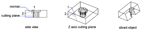
- Specify a point on the section plane. Sets a point on the slicing plane.
- Specify a point on the Z-axis (normal) of the plane. Specifies a point that defines the axis that is perpendicular to the slicing plane.
- View
-
Aligns the cutting plane with the current viewport's viewing plane. Specifying a point defines the location of the cutting plane.
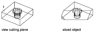
- Specify a point on the current view plane. Sets a point on the object to start the slice.
- XY
-
Aligns the cutting plane with the XY plane of the current user coordinate system (UCS). Specifying a point defines the location of the cutting plane.
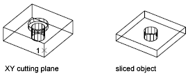
- Point on the XY-plane. Sets the location of the slice.
- YZ
-
Aligns the cutting plane with the YZ plane of the current UCS. Specifying a point defines the location of the cutting plane.
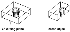
- Point on the YZ-plane. Sets the location of the slice.
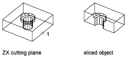
- ZX
-
Aligns the cutting plane with the ZX plane of the current UCS. Specifying a point defines the location of the cutting plane.
- Point on the ZX-plane. Sets the location of the slice.
If a single object is sliced into more than two objects, one solid or surface is created from the objects on one side of the plane and another solid or surface is created from the objects on the other side.
- Point on the ZX-plane. Sets the location of the slice.
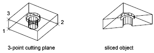
- 3points
-
Defines the cutting plane using three points.
- Point on desired side
-
Uses a point to determine which side of the sliced solids your drawing retains. The point cannot lie on the cutting plane.
- Keep both sides
-
Retains both sides of the sliced solids. Slicing a single solid into two pieces creates two solids from the pieces on either side of the plane. SLICE never creates more than two new composite solids for each selected solid.