This next operation machines an external thread (M20x2.5) on the front part of the stub axle. Use the Thread strategy to generate the toolpath for the threading operation.
- On the ribbon, click
CAM tab
 Turning panel
Thread
Turning panel
Thread
 .
.
 Tool tab
- On the Tool tab, click
 .
. - Click the
 button to add a new tool for the threading operation.
 - On the Insert tab, select Threading from the Type: drop-down menu. Then, select ISO Triangular Full Profile from the Shape: drop-down menu for the insert. Set the Thread pitch to 2.5 mm (M20x2.5). Leave the rest of the values at their defaults.
- On the Holder tab, from the Style: drop-down menu, select the Straight Threading holder with the default values.
- Click the
 button to create your new tool.
 - Click
 to close the Tool Library dialog.
 Geometry tab
- Click the Geometry tab.
- Click the Thread faces button and select the face of the part (shown below) where the thread operation is to be performed.
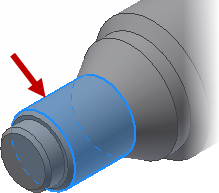
The selected thread face
Because the threads do not cover the entire selected area, it is necessary to define a confinement for the operation.
- Enable the Confinement group.
- Change Frontside stock offset to: 0 mm
- Change Backside stock offset to: -2 mm
 Passes tab
- Click the Passes tab.
- Select Right handed from the Threading hand: drop-down menu.
- Change Thread depth to: 2 mm
- Change Thread pitch to: 2.5 mm
- Since the thread does not end in a groove, ensure that the Fade thread end check box is enabled to fade out the thread at the end.
- Change Number of stepdowns: to: 8
Start the Calculation
- Click at the bottom of the Operation dialog box, or right-click in the graphics window and select OK from the marking menu, to automatically start calculating the toolpath.
The toolpath is now calculated and a preview appears in the graphics window.
Continue to To Cut Off the Part...