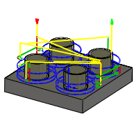
Select same diameter
Check this to automatically select all holes with the same diameter as the hole currently selected in the selection box.
Example: To drill a single 6 mm / 1/4" hole and all 12 mm / 1/2" holes, first select the 6 mm / 1/4" hole, then select one of the 12 mm / 1/2" holes, and then check the Select same diameter option.
Using this option is associative to the model. If additional holes with the same diameter are added later, regenerating the operation automatically includes the added holes in the drilling cycle.
Auto-merge hole segments
When drilling a hole with multiple segments, enable to have neighboring segments included automatically.
Dwelling period:
Dwelling time in seconds.
Specifying a dwell time halts all axis movement for a specified time while the spindle continues revolving at the specified rpm. This can be used to ensure that chips are cleared before retracting from a hole, and will typically improve the finish of a hole.
Typically a dwelling time between 1/4 second and 1 second is sufficient.
Example: To dwell for 1/4 second, specify 0.25 or 1/4 in this field.
When post processing a drill cycle, the dwell time is specified as one of the drill cycle parameters (typically P), and in most cases it is output in milliseconds (ms).
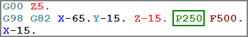
250ms dwell time in G82
When posting using expanded cycles, the dwell time is output as a regular dwell command (G4).
To calculate the minimum dwell time that ensures at least one complete revolution, use a value of 60 divided by the spindle speed.
Example: At 350 RPM the minimum dwell time should be 60 / 350 = 0.171s (which could be rounded to 0.2s).
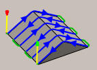
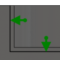
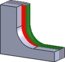
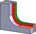
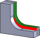
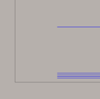
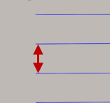
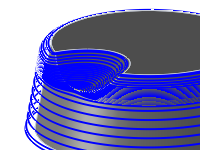
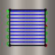
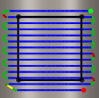
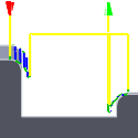
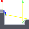
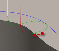
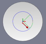
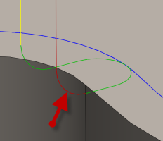
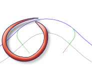
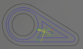
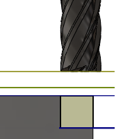
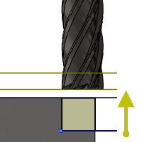
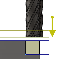
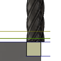
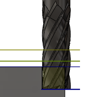
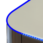
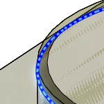
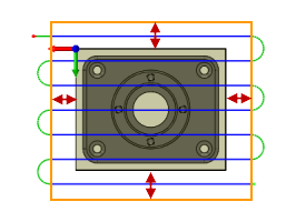
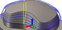
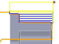
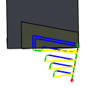
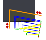
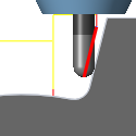
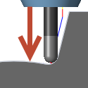
Finishing overlap:
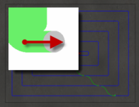
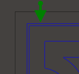
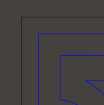
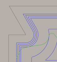
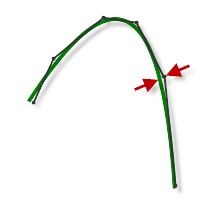
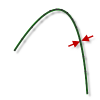
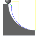
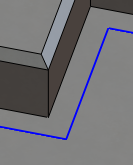
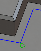
The finishing overlap is the distance that the tool passes beyond the entry point before leading out.
Specifying a finishing overlap ensures that the material at the entry point is properly cleared.
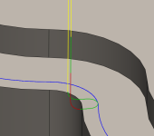
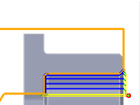
No finishing overlap
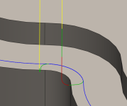
0.25" finishing overlap
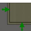
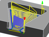
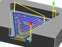
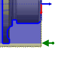
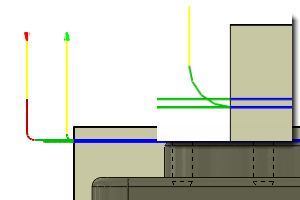
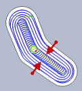
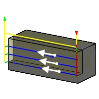
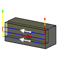
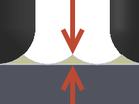
Use thin wall
When milling part features with wall thicknesses comparable to sheet metal stock, or even thinner, the stock is subjected to the forces generated by metal removal. This can result in the delicate structure of thin walls moving relative to the tool, making it difficult to maintain dimensional accuracy and impart the specified surface finish.
This option can be used to reduce the vibration and chatter by ensuring that both sides of a thin wall are machined at the same time.
Thin wall width:
The width of walls that should be considered thin walls.
Any wall with this width or thinner is machined on both sides at the same time to reduce vibration and chatter.
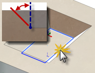
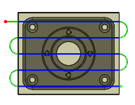
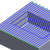
Direction
The direction option lets you control if Inventor HSM should attempt to maintain either Climb or Conventional milling.
Climb
Both Ways
Climb
Select Climb to machine all the passes in a single direction. When this method is used, Inventor HSM attempts to use climb milling relative to the selected boundaries.
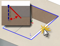
Conventional
This reverses the direction of the toolpath compared to the Climb setting to generate a conventional milling toolpath.
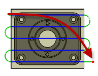
Both Ways
When Both ways is selected, Inventor HSM disregards the machining direction and links passes with the directions that result in the shortest toolpath.
Direction
Specifies if material is removed using Conventional Milling or Climb Milling, or a combination of both.
Conventional Milling
Climb Milling
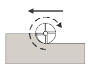
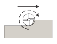
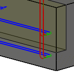
Climb vs. Conventional Milling
Milling tools advance through the material so that the cutting flutes engage the material at maximum thickness and then decrease to zero. This is called Climb Milling.
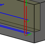
Cutting in the opposite direction causes the tool to scoop up the material, starting at zero thickness and increasing to maximum. This is called Conventional milling.
Conventional milling is often used on manual machines because backlash in the machine lead screws causes the tool to lurch when climb cutting. This is not a problem on CNC machines because they use ball screws.
Conventional milling causes the tool to rub against the cutting surface, work hardening the material, generating heat, and increasing tool wear. Raking chips across the finished surface also produces a poorer surface finish.
Unless specifically recommended by the tool manufacturer for the material being milled, always use climb milling on a CNC. Climb milling produces far less cutting pressure and heat, leaves a better surface finish, and results in longer tool life.
Stock to Leave
Positive
Positive Stock to Leave - The amount of stock left after an operation to be removed by subsequent roughing or finishing operations. For roughing operations, the default is to leave a small amount of material.

None
No Stock to Leave - Remove all excess material up to the selected geometry.
Negative
Negative Stock to Leave - Removes material beyond the part surface or boundary. This technique is often used in Electrode Machining to allow for a spark gap, or to meet tolerance requirements of a part.
Radial (wall) stock to leave
The Radial stock to leave parameter controls the amount of material to leave in the radial (perpendicular to the tool axis) direction, i.e. at the side of the tool.
Radial stock to leave
Radial and axial stock to leave
Specifying a positive radial stock to leave results in material being left on the vertical walls and steep areas of the part.
For surfaces that are not exactly vertical, Inventor HSM interpolates between the axial (floor) and radial stock to leave values, so the stock left in the radial direction on these surfaces might be different from the specified value, depending on surface slope and the axial stock to leave value.
Changing the radial stock to leave automatically sets the axial stock to leave to the same amount, unless you manually enter the axial stock to leave.
For finishing operations, the default value is 0 mm / 0 in, i.e. no material is left.
For roughing operations, the default is to leave a small amount of material that can then be removed later by one or more finishing operations.
Negative stock to leave
When using a negative stock to leave, the machining operation removes more material from your stock than your model shape. This can be used to machine electrodes with a spark gap, where the size of the spark gap is equal to the negative stock to leave.
Both the radial and axial stock to leave can be negative numbers. However, the negative radial stock to leave must be less than the tool radius.
When using a ball or radius cutter with a negative radial stock to leave that is greater than the corner radius, the negative axial stock to leave must be less than or equal to the corner radius.
Axial (floor) stock to leave
The Axial stock to leave parameter controls the amount of material to leave in the axial (along the Z-axis) direction, i.e. at the end of the tool.
Axial stock to leave
Both radial and axial stock to leave
Specifying a positive axial stock to leave results in material being left on the shallow areas of the part.
For surfaces that are not exactly horizontal, Inventor HSM interpolates between the axial and radial (wall) stock to leave values, so the stock left in the axial direction on these surfaces might be different from the specified value depending on surface slope and the radial stock to leave value.
Changing the radial stock to leave automatically sets the axial stock to leave to the same amount, unless you manually enter the axial stock to leave.
For finishing operations, the default value is 0 mm / 0 in, i.e. no material is left.
For roughing operations, the default is to leave a small amount of material that can then be removed later by one or more finishing operations.
Negative stock to leave
When using a negative stock to leave the machining operation removes more material from your stock than your model shape. This can be used to machine electrodes with a spark gap, where the size of the spark gap is equal to the negative stock to leave.
Both the radial and axial stock to leave can be negative numbers. However, when using a ball or radius cutter with a negative radial stock to leave that is greater than the corner radius, the negative axial stock to leave must be less than or equal to the corner radius.
Geometry
Allows you to select the drill positions from points (vertices, sketch points, etc.), sketches containing points, arcs (sketch or solid edges), or cylindrical faces.
Remove Duplicate Holes
Specifies that duplicate holes should be removed.
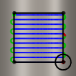
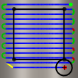
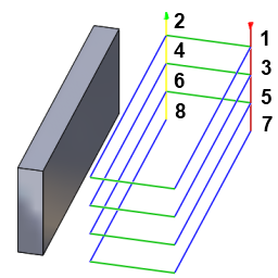
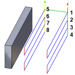
Order by depth
Specifies that the passes should be ordered top down.
Order by depth disabled
Order by depth enabled
Order by depth
Specifies that the holes must be ordered by either increasing or decreasing Z-level.
Order by area
Toolpaths are ordered by area rather than by depth.
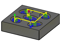
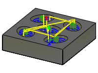
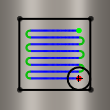
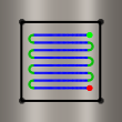
Optimize order
Specifies that the holes should be ordered such that the machining distance is minimized.
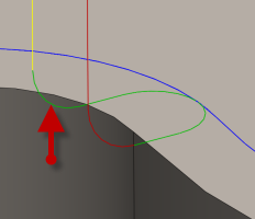
Drill tip through bottom
Enable to make the tool tip drill completely through the bottom.
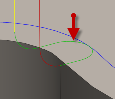
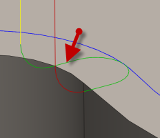
Break-through depth
Specifies how far the tool drills past the bottom of the hole to ensure through-cutting.
Cycle type
The type of drilling cycle.
Inventor HSM provides a number of pre-defined (canned) drilling cycles.
Selecting a drill cycle determines which parameters can be specified for the drilling operation.
- Drilling - rapid out - Regular drilling recommended for drilling holes with depths of less than three times the tool diameter.
- Counterboring - dwell and rapid out - Enlarges one end of a previously drilled hole, the enlarged end normally ends in a flat interior. A dwell is used to improve the finish of a hole.
- Chip breaking - partial retract - Drills holes with depths of more than three or four times the tool diameter, by periodically retracting the tool to clear chips and/or flood the hole with coolant. This is also known as Peck drilling.
- Deep drilling - full retract - Drills holes with depths of more than three or four times the tool diameter, by periodically retracting the tool out of the hole to clear chips and/or flood the hole with coolant. This is also known as Peck drilling.
- Break through - Allows for reduced feed and speed before breaking through a hole.
- Guided deep drilling - gun drilling - A standard gun drill has a single effective cutting edge. This unique head geometry is different from a conventional twist drill. While drilling, guide pads burnish the hole allowing the hole to maintain straightness. The result of this activity is a very round hole with a precision diameter that can also produce deep, straight holes in a variety of materials.
- Tapping - Taps right or left internal threads in a round hole with a multi-point tool.
- Left tapping - A tap that rotates counterclockwise as it enters the hole to cut a thread.
- Right tapping - A tap that rotates clockwise as it enters the hole to cut a thread.
- Tapping with chip breaking - Tapping with chip breaking.
- Reaming - Reaming (G85 style) with feed out.
- Boring - Boring with dwell at bottom and feed out.
- Stop boring - Boring (G86 style) with spindle stop at the bottom and rapid out.
- Fine boring - Fine boring with shift away from the hole side.
- Back-boring - Boring from the back.
- Circular pocket milling
- Bore milling
- Thread milling
- Probe - Used to measure a feature on the part with a probe tool, or use macros from the machine to define the WCS. Needs special handling in the post processors depending on the machine.
Pecking depth:
Sets the depth for the first peck move, which plunges in and out of the material to clear and break chips.
Pecking depth reduction:
The amount by which the pecking depth is reduced per peck.
Minimum pecking depth:
The minimum allowed pecking depth.
Accumulated pecking depth:
Specifies the pecking depth which forces full retract.
Chip break distance:
With a chip breaking operation, the drill withdraws a specified distance after advancing into the hole to prevent the binding of chips.
Dwell before retract
Enables dwelling before pecking retracts to thin out chips. This can increase tool lift significantly depending on the material being machined.
Boring Shift
Sets the distance that a boring bar tool moves away from the wall of the toolpath before retracting to prevent gouging. This option only applies to bore bar drill cycles.
Compensation Direction
Specifies the compensation direction.
Sideways compensation:
Specifies the compensation direction.
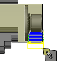
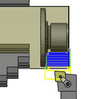
- Left (climb milling)
- Right (conventional milling)
Compensation type:
Specifies the compensation type.
- In computer - Tool compensation is calculated automatically by Inventor HSM, based on the selected tool diameter. The post-processed output contains the compensated path directly, instead of G41/G42 codes.
- In control - Tool compensation is not calculated, but rather G41/G42 codes are output to allow the operator to set the compensation amount and wear on the machine tool control.
- Wear - Works as if In computer was selected, but also outputs the G41/G42 codes. This lets the machine tool operator adjust for tool wear at the machine tool control by entering the difference in tool size as a negative number.
- Inverse wear - Identical to the Wear option, except that the wear adjustment is entered as a positive number.
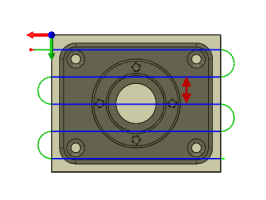
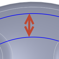
Maximum stepover:
Specifies the maximum stepover value.
Maximum horizontal stepover
Specifies the maximum horizontal stepover between passes.
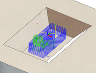
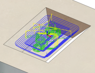
Adaptive clearing
Legacy 2D clearing
Smoothing deviation:
The maximum amount of smoothing applied to the roughing passes. Use this parameter to avoid sharp corners in the toolpath.

Corner deviation
The maximum corner deviation. Use this parameter to avoid sharp corners in the toolpath.

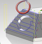
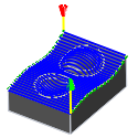
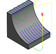
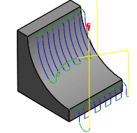
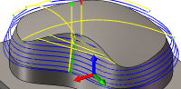
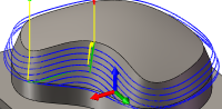
Finishing passes
Enable to perform finishing passes using the side of the tool.
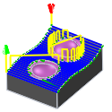
With Finishing passes
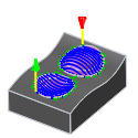
Without Finishing passes
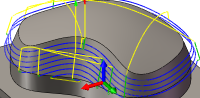
Number of finishing passes:
Specifies the number of finishing passes.
Shown with three finishing passes
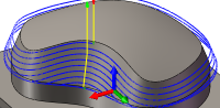
Stepover:
The maximum distance between finishing passes.
Leads on all finishing passes
Forces a full lead in and out on every finishing pass.
Enabled
Disabled
Repeat finishing pass
Enable to perform the final finishing pass twice to remove stock left due to tool deflection.
Rough stock to leave:
Specifies the amount of radial stock to leave for the roughing pass.
Multiple Depths
Specifies that multiple depths should be taken.
With Multiple Depth cuts
Without Multiple Depth cuts
Maximum stepdown:
Specifies the maximum stepdown between Z-levels.
Finishing stepdowns:
The number of finishing passes using the bottom of the tool.
Shown with three finishing passes
Finishing stepdown:
The size of each stepdown in the finishing passes.
Finishing stepdown
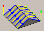
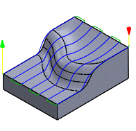
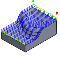
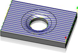
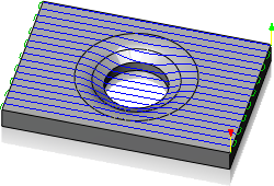
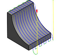
Wall taper angle (deg):
Specifies the taper angle of the walls.
Defining a slope angle can be used to machine features with a 2D strategy that would have otherwise required a 3D strategy.
Slope angle @ 0 degrees
Slope angle @ 45 degrees
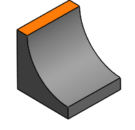
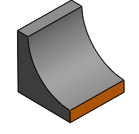
Geometry Selection
Bottom Selection
Top Selection
Finish only at final depth
Perform finishing passes only at the final depth to avoid leaving marks on the walls.
Disabled
Enabled
Rough final
Enable to apply a finishing stepdown to every roughing pass/finishing pass when doing multiple depths with one or more finishing stepdowns.
Tolerance:
The machining tolerance is the sum of the tolerances used for toolpath generation and geometry triangulation. Any additional filtering tolerances must be added to this tolerance to get the total tolerance.
Loose Tolerance .100
Tight Tolerance .001
CNC machine contouring motion is controlled using line G1 and arc G2 G3 commands. To accommodate this, CAM approximates spline and surface toolpaths by linearizing them; creating many short line segments to approximate the desired shape. How accurately the toolpath matches the desired shape depends largely on the number of lines used. More lines result in a toolpath that more closely approximates the nominal shape of the spline or surface.
Data Starving
It is tempting to always use very tight tolerances, but there are trade-offs including longer toolpath calculation times, large G-code files, and very short line moves. The first two are not much of a problem because Inventor HSM calculates very quickly and most modern controls have at least 1MB of RAM. However, short line moves, coupled with high feedrates, may result in a phenomenon known as data starving.
Data starving occurs when the control becomes so overwhelmed with data that it cannot keep up. CNC controls can only process a finite number of lines of code (blocks) per second. That can be as few as 40 blocks/second on older machines and 1,000 blocks/second or more on a newer machine like the Haas Automation control. Short line moves and high feedrates can force the processing rate beyond what the control can handle. When that happens, the machine must pause after each move and wait for the next servo command from the control.
Multiple finishing passes
Enable to perform multiple finishing passes.
Finishing Smoothing Deviation
The maximum amount of smoothing applied to the finishing passes. Use this parameter to avoid sharp corners in the toolpath. Setting this parameter leaves more stock than requested at the contour corners.
Roughing Passes
Enable to perform roughing passes.
Roughing clearing pass
Specifies that any cusps left by the roughing passes should be cleared. Enable this setting to avoid tool collision with leftover stock after the roughing passes at walls.
Stepover:
Specifies the horizontal stepover between passes. By default, this value is 95% of the cutter diameter less the tool corner radius.
Horizontal stepover
Spiral stepover:
Specifies the radial stepover between passes. The system default is based on 50% of the cutter diameter.
Spiral stepover
Stepover
The stepover between passes measured along the surface.
Chamfer width:
The (additional) width of the chamfer.
For edges that are not already chamfered, this is the final width of the chamfer.
For chamfered edges, this is an additional offset; similar to using negative radial stock to leave.
Chamfer tip offset:
This is added to the toolpath depth, while keeping the tool in contact with the selected edge by adjusting the toolpath radial offset.
Pass direction:
Specifies the direction of the passes.
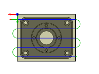
Pass direction @ 0°
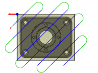
Pass direction @ 45°
Pass extension:
Distance to extend the passes beyond the machining boundary.
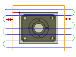
Pass extension
Bottom
The maximum cutting depth.
Top
Specifies the top of the stock.
Optimal load:
Specifies the amount of engagement the adaptive strategies should maintain.
High Speed Clearing Toolpath
Legacy Clearing Toolpath
Load Deviation
The maximum deviation of the optimal tool load. The load is never higher than the optimal load plus the deviation.
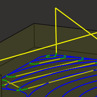
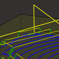
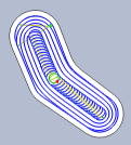
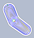
Minimum cutting radius:
With Minimum cutting radius set
With Minimum cutting radius set - sharp corners in the toolpath are avoided minimizing chatter in finished parts.
Without Minimum cutting radius set
Without Minimum cutting radius set - the toolpath attempts to remove material anywhere the selected tool can reach. This produces sharp corners in the toolpath that often leads to chatter in the machined part.
Fine stepdown:
Specifies the fine stepdown for intermediate steps. These steps are upwards in the direction of the tool axis.
Round walls
Enable to round the extruded walls.
Machine cavities
Enable to machine on the inside of the selected closed contours.
Disable to machine on the outside of the selected closed contours.
Open contours may only be specified when this option is enabled.
Machine cavities enabled
Machine cavities disabled
Machine cavities
If enabled, the strategy ramps into pockets and machines these.
If disabled, the strategy only machines from the outside-in and leaves pockets unmachined.
Manual stepover
Enable to set the stepover manually.
Minimum stepover:
Specifies the minimum stepover.
Prevent Full-Width Cuts
Specifies that full-width cuts should be avoided.
Maximum Tool Engagement
Specifies the maximum tool engagement for full-width cuts.
Maximum Trochoidal Radius
Specifies the maximum trochoidal radius.
Machine shallow areas
Specifies that additional Z-levels should be cuts at shallow areas. The following two images are shown with 3D Contour.
Disabled
Enabled
Minimum shallow stepdown:
This parameter controls the minimum allowed stepdown between the extra Z-levels. It takes precedence over the Maximum shallow stepover value.
Maximum shallow stepover:
This parameter controls the stepover used to detect areas where extra Z-levels should be inserted. If the normal stepdown results in a stepover of more than this value, extra levels are inserted until the stepover or the minimum stepdown is reached.
Flat area detection
If enabled, the strategy attempts to detect the heights of flat areas and peaks, and machine at these levels.
If disabled, the strategy machines at exactly the specified stepdowns.
Minimum Stepdown
Used when detecting flat areas. This is the smallest allowable stepdown to make.
Minimum axial engagement:
Enable to ensure that at least one flute is constantly engaged as it turns during the intermediate steps to avoid chatter and reduce tool wear.
Axial offset:
Specifies an axial offset value for the toolpath for the chosen contour.
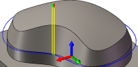
Axial offset passes
Enable to do multiple depth cuts.
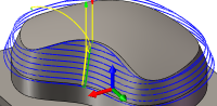
Axial offset passes are used to create multiple incremental Z offset passes in many of the 3D finishing strategies. They work much like multiple finishing stepdowns in the 2D operations and are useful for removing a fixed amount of stock using several passes. The following images are shown with 3D Parallel.
Disabled
Three axial offset passes
Maximum roughing stepdown:
Specifies the maximum stepdown between Z-levels for roughing.
Maximum stepdown - shown without finishing stepdowns
Number of stepdowns:
Specifies the desired number of stepdowns.
Overthickness:
Additional thickness that is applied to the tool to detect passes along fillets with a radius exceeding the radius of the tool.
Bitangency angle:
An angle in degrees that is used to detect passes along a wall or fold.
Limit number of stepovers
When disabled, the number of steps is unlimited, and the result is a collapsed pencil finish of the entire surface.
Link from inside to outside
Enable to specify whether the linking between passes should be done without particular ordering or linking should be done by ordering from inside passes to outside passes.
Inside/outside direction:
Specifies if the toolpath moves inside-out or outside-in. Selecting the Don't care option minimizes the ordering by distance.
Inside > out
Outside > in
Angular step:
The angular step in degrees between radial passes.
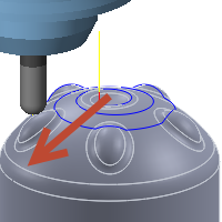
Angle from:
The radial starting angle in degrees measured from the X axis as viewed from the WCS.
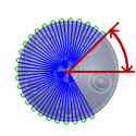
From Angle
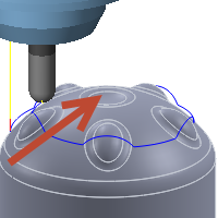
Angle to:
The radial ending angle in degrees measured from the X axis as viewed from the WCS.
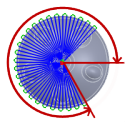
To angle
Inner radius:
Sets the minimum inner radius. The following images are shown with a 3D Spiral toolpath.
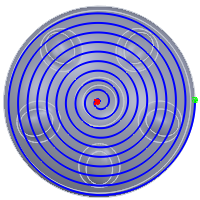
No inner radius
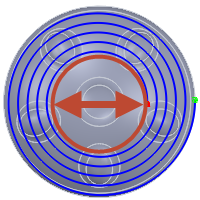
Inner radius
Outer radius:
Sets the maximum outer radius. The following images are shown with a 3D Spiral toolpath.
No outer radius
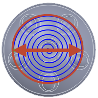
Outer radius
Manual Center
The center of the radial passes.
Clockwise
Specifies that the spiral is clockwise.
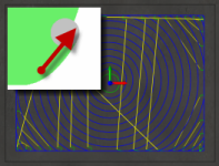
Tool Orientation
Specifies the orientation of the turning tool in degrees.
Tool orientation
Overrides the tool orientation defined in the setup
Works with all 2D and 3D operations to control 3 + 2 Axis programming.
Tool orientation enabled
Tool orientation disabled
Tool Orientation
Specifies how the tool orientation is determined using a combination of triad orientation and origin options.
The Orientation drop-down menu provides the following options to set the orientation of the X, Y, and Z triad axes:
- Setup WCS orientation - Uses the workpiece coordinate system (WCS) of the current setup for the tool orientation.
- Model orientation - Uses the coordinate system (WCS) of the current part for the tool orientation.
- Select Z axis/plane & X axis - Select a face or an edge to define the Z axis and another face or edge to define the X axis. Both the Z and X axes can be flipped 180 degrees.
- Select Z axis/plane & Y axis - Select a face or an edge to define the Z axis and another face or edge to define the Y axis. Both the Z and Y axes can be flipped 180 degrees.
- Select X & Y axes - Select a face or an edge to define the X axis and another face or edge to define the Y axis. Both the X and Y axes can be flipped 180 degrees.
- Select coordinate system - Sets a specific tool orientation for this operation from an Inventor User Coordinate System (UCS) in the model. This uses both the origin and orientation of the existing coordinate system. Use this if your model does not contain a suitable point & plane for your operation.
- Use axis substitution - For 4 axis machining, axis substitution creates a toolpath by using a reference radius and unwrapping the round part to generate the toolpath.
The Origin drop-down menu offers the following options for locating the triad origin:
- Setup WCS origin - Uses the workpiece coordinate system (WCS) origin of the current setup for the tool origin.
- Model origin - Uses the coordinate system (WCS) origin of the current part for the tool origin.
- Selected point - Select a vertex or an edge for the triad origin.
- Stock box point - Select a point on the stock bounding box for the triad origin.
- Model box point - Select a point on the model bounding box for the triad origin.
Tool orientation
Specifies how the workpiece coordinate system is specified.
Origin & Orientation
Use Origin & Orientation - A sketch point or stock vertex is used to defined the location of the WCS, and a plane or planar face is used to define the orientation of the WCS.
Coordinate System
Use Coordinate System - An existing Inventor user coordinate system (UCS) is used to define both the location and orientation of the WCS.
Stock & Orientation
Use Stock & Orientation - A location on the stock (example: Top Center) is used to define the location of the WCS, and a plane or planar face is used to define the orientation of the WCS.
Model
Enable to override the model geometry (surfaces/bodies) defined in the setup.
Include setup model
Enabled by default, the model selected in the setup is included in addition to the model surfaces selected in the operation. If you disable this check box, then the toolpath is generated only on the surfaces selected in the operation.
Geometry
Select any sketch feature, or try To Select Open or Closed Contours from the model to form open or closed contours for machining.
Geometry
You can specify specific target part surfaces here.
- Setup Model uses all available geometry in the part or assembly, or as specified in the creation of a Setup Reference.
- Selection uses only the bodies, faces, or surfaces that are selected.
Note that bodies are selected by default.
If you want to select individual faces instead, you need to use either Select Other or change the selection filter to select only faces.
Avoid/Touch Surfaces
Specifies surfaces to avoid. When enabled, toolpaths stay away from the selected surfaces by a specified amount.
Disabled
Enabled
Clearance:
The tool always stays this distance from the selected surfaces.
Touch surfaces
Inverts the meaning of the Avoid surfaces setting. When enabled, the avoid surfaces are the ones that must be touched within the given clearance while the remaining surfaces are avoided.
Touch surfaces
Up/down milling:
Use this option to break each pass into segments so that each piece is machined using either downward or upward moves only. This is useful when using insert cutters that are restricted to a specific cutting direction.

Don't Care
Down Milling
Machining boundary:
Boundaries mode specifies how the toolpath boundary is defined. The following images are shown using a 3D Radial toolpath.
Example 1
Example 2
Boundary modes:
- None - The toolpaths machine all stock without limitation.
- Bounding box - Contains toolpaths within a box defined by the maximum extents of the part as viewed from the WCS.
-

Bounding box
- Silhouette - Contains toolpaths within a boundary defined by the part shadow as viewed from the WCS.
Silhouette
- Selection - Contains toolpaths within a region specified by a selected boundary.
Selection
Tool containment:
Use tool containment to control the tools' position in relation to the selected boundary or boundaries.
Inside
The entire tool stays inside the boundary. As a result, the entire surface contained by the boundary might not be machined.
Inside
Center
The boundary limits the center of the tool. This setting ensures that the entire surface inside the boundary is machined. However, areas outside the boundary or boundaries might also be machined.
Center
Outside
The toolpath is created inside the boundary, but the tool edge can move on the outside edge of the boundary.
Outside
To offset the boundary containment, use the Additional Offset parameter.
Additional offset:
The additional offset is applied to the selected boundary/boundaries and tool containment.
A positive value offsets the boundary outwards unless the tool containment is Inside, in which case a positive value offsets inwards.
Negative offset with tool center on boundary
No offset with tool center on boundary
Positive offset with tool center on boundary
To ensure that the edge of the tool overlaps the boundary, select the Outside tool containment method and specify a small positive value.
To ensure that the edge of the tool is completely clear of the boundary, select the Inside tool containment method and specify a small positive value.
Contact point boundary
When enabled, specifies that the boundary limits where the tool touches the part rather than the tool center location.
Disabled
Enabled
The difference is illustrated below on a parallel toolpath using a ball end mill.
Disabled

Enabled
Contact only
Controls whether or not toolpaths are generated where the tool is not in contact with the machining surface. When disabled, toolpaths are extended to the limits of the containment boundary and across openings in the workpiece.
Enabled
Disabled
Slope
Contains toolpaths based on a range of specified angles.
0° - 90°
0° - 45°
45° - 90°
Slope angle confinement is specified by the From slope angle and To slope angle angle parameters on the Geometry tab. Angles are defined from 0° (horizontal) to 90° (vertical).
Only areas equal to or greater than the values in the From slope angle and To slope angle parameters are machined.
Most 3D finishing strategies support slope angle confinement. One use of slope confinement is to confine a selected toolpath strategy to angles where it works best. For example, Parallel Finish is better suited to shallow areas while Contour Finish is better suited to steep areas.
From slope angle:
From slope angle is defined from the 0° (horizontal) plane. Only areas equal to or greater than this value are machined.
Slope angle from 0°
To slope angle:
To slope angle is defined from the 0° (horizontal) plane. Only areas equal to or less than this value are machined.
Slope angle to 90°
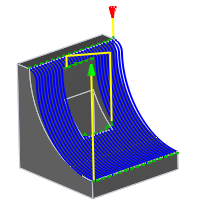
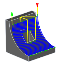
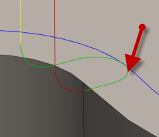
Retraction policy:
Controls how the tool moves between cutting passes. The following images are shown using the Flow strategy.
- Full retraction - completely retracts the tool to the Retract Height at the end of the pass before moving above the start of the next pass.
- Minimum retraction - moves straight up to the lowest height where the tool clears the workpiece, plus any specified safe distance.

- Shortest path - moves the tool the shortest possible distance in a straight line between paths.
Caution: The Shortest path option should not be used on machines that do not support linearized rapid movements where G0 moves are straight-line (versus G0 moves that drive all axes at maximum speed, sometimes referred to as "dogleg" moves). Failure to obey this rule will result in machine motion that cannot be properly simulated by the software and may result in tool crashes.For CNC machines that do not support linearized rapid moves, the post processor can be modified to convert all G0 moves to high-feed G1 moves. Contact technical support for more information or instructions how to modify post processors as described.
High feedrate mode:
Specifies when rapid movements should be output as true rapids (G0) and when they should be output as high feedrate movements (G1).
- Preserve rapid movement - All rapid movements are preserved.
- Preserve axial and radial rapid movement - Rapid movements moving only horizontally (radial) or vertically (axial) are output as true rapids.
- Preserve axial rapid movement - Only rapid movements moving vertically.
- Preserve radial rapid movement - Only rapid movements moving horizontally.
- Preserve single axis rapid movement - Only rapid movements moving in one axis (X, Y or Z).
-
Always use high feed - Outputs rapid movements as (high feed moves) G01 moves instead of rapid movements (G0)
This parameter is usually set to avoid collisions at rapids on machines which perform "dog-leg" movements at rapid.
High feedrate:
The feedrate to use for rapids movements output as G1 instead of G0.
Allow rapid retract
Pull away before retract
Enable to move away from the stock before retracting when possible. By disabling this option, retracts will touch the stock.
When enabled, retracts are done as rapid movements (G0). Disable to force retracts at lead-out feedrate.
Safe distance:
Minimum distance between the tool and the part surfaces during retract moves. The distance is measured after stock to leave has been applied, so if a negative stock to leave is used, special care should be taken to ensure that safe distance is large enough to prevent any collisions.
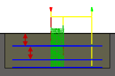
Maximum stay-down distance:
Specifies the maximum distance allowed for stay-down moves.
1" Maximum stay-down distance
2" Maximum stay-down distance
Stay-down level:
Use this setting to control when to stay down rather than doing retracts when moving around obstacles. Generally, you will want the Adaptive strategy to stay-down more if your CNC machine does slow retracts compared to high feed moves. In such cases, increase the level value in the Stay-down level: drop-down menu. Values increase by increments of 10% with the Least setting at 0% and the Most setting at 100%.
Set minimum profile diameter
This allows a minimum profile diameter to be set. If a machining area is smaller than the specified minimum profile diameter, then it is not machined.
Minimum profile diameter:
Specifies the minimum cavity to be cut.
Direction:
The Direction option lets you control if Inventor HSM should try to maintain either Climb or Conventional milling.
Climb
Select Climb to machine all the passes in a single direction. When this method is used, Inventor HSM attempts to use climb milling relative to the selected boundaries.
Climb
Conventional
This reverses the direction of the toolpath compared to the Climb setting to generate a conventional milling toolpath.
Conventional
Use helical leads
Enable to use helical lead in/out movements instead of circular lead in/out movements.
Keep tool down
When enabled, the strategy avoids retracting when the distance to the next area is below the specified stay-down distance.
Both ways
When enabled, passes are done in both directions. Disable to force climb-only machining.
Lead mode:
The lead mode settings provide very specific control of the leads. There are five options available.
- Fail - Results in a failure if it is not possible to do the lead in/outs without causing a gouge. User intervention is then required to make the leads fit.
- Discard passes - Discards any passes that cannot be reached with the given settings. This option leaves rest material for any following operations.
- Move lead - Moves the lead position to a different location along the part until there is room, but keeps the lead as specified.
- Turn lead - Changes the lead angle until there is room.
- Retract lead - Is the most automatic lead mode and also the default setting. It allows linking of all parts and, in some cases, does radial retracts when there is no other alternative. This is the recommended setting.
Use fixed lead direction
Specifies that the given lead directions are always relative to the XZ coordinate system. When disabled, the leads are relative to the front/back cutting direction of the individual pass.
Lead-in (entry)
Enable to generate a lead-in.
Lead-in
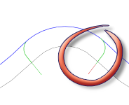
Horizontal lead-in radius:
Specifies the radius for horizontal lead-in moves.
Horizontal lead-in radius
Lead-in sweep angle:
Specifies the sweep of the lead-in arc.
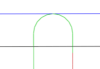
Sweep angle @ 90 degrees
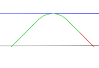
Sweep angle @ 45 degrees
Linear lead-in distance:
Specifies the length of the linear lead-in move for which to activate radius compensation in the controller.
Linear lead-in distance
Perpendicular
Replaces tangential extensions of lead-in/lead-out arcs with a move perpendicular to the arc.
Shown with Perpendicular entry/exit
Example: A bore that has lead arcs that are as large as possible (the larger the arc the less chance of dwell mark), and where a tangent linear lead is not possible because it would extend into the side of the bore.
Vertical lead-in radius:
The radius of the vertical arc smoothing the entry move as it goes from the entry move to the toolpath itself.
Vertical lead-in radius
Lead-out (exit)
Enable to generate a lead-out.
Lead-out
Same as lead-in
Specifies that the lead-out definition should be identical to the lead-in definition.
Horizontal lead-out radius:
Specifies the radius for horizontal lead-out moves.
Horizontal lead-out radius
Lead-out sweep angle:
Specifies the sweep of the lead-out arc.
Linear lead-out distance:
Specifies the length of the linear lead-out move for which to deactivate radius compensation in the controller.
Linear lead-out distance
Perpendicular
Replaces tangential extensions of lead-in/lead-out arcs with a move perpendicular to the arc.
Shown with Perpendicular entry/exit
Example: A bore that has lead arcs that are as large as possible (the larger the arc the less chance of dwell mark), and where a tangent linear lead is not possible because it would extend into the side of the bore.
Vertical lead-out radius:
Specifies the radius of the vertical lead-out.
Vertical lead-out radius
Ramp
Enable ramps.
Shown with a 15 degree Ramp angle
Ramp type:
Specifies how the cutter moves down for each depth cut.
Predrill
To use the Predrill option, Predrill location(s) must be defined.
Plunge
Zig-Zag
Notice the smooth transitions on the Zig-Zag ramp type.
Profile
Smooth Profile
Helix
Transition type:
Specifies the type of connection done between passes.
- No contact - Sidesteps are not connected with each other on the same Z-level, but connected with a retract move.
- Straight line - Simpler, direct connections using straight lines.
- Shortest path - The shortest possible path between machining areas - typically a move in a straight line.
- Smooth - Use smooth tangential movements using true arcs where appropriate.
Allow plunging
Enable to allow vertical plunging. This disables all other types of vertical leads, and causes the machine to move vertically down to the next machining level at the plunge rate specified for the tool.
Allow helical ramps
When enabled, helical ramps are generated whenever possible.
Allow contour ramps
When enabled, contour ramps (or profile ramps) are generated.
Allow smooth contour ramps
When enabled, smoothed contour ramps are generated.
Allow zig-zag ramps
When enabled, zig-zag ramps are generated.
Allow plunging outside stock
Instead of machining the material inside the contour of a selected area, enabling this parameter allows you to remove the material outside the selected contour, by picking an additional stock contour.
Disable this parameter to force ramping in stock.
Ramping angle (deg):
Specifies the maximum ramping angle.
Ramp taper angle (deg):
The desired taper angle of the helical ramps. Use this setting to keep the tool shaft slightly away from the stock and improve chip escape during ramping.
Maximum ramp stepdown:
Specifies the maximum stepdown per revolution on the ramping profile. This parameter allows the tool load to be constrained when doing full-width cuts during ramping.
Ramp clearance height:
Height of ramp over the current stock level.
Ramp radial clearance:
Specifies the minimum distance to the contour for the lead-in helix.
Helical ramp diameter:
Specifies the helical ramp diameter.
Smooth ramps
When enabled, ramps are started and ended tangentially in all three axes.
Ramping is done without discontinuities in the first order derivative so that smooth curves are used instead of the usual kinks in the path.
Minimum ramp diameter:
Specifies the minimum ramp diameter.
Force profile ramp
Enable this to force a profile ramp on top of the selected contour(s).
Use this when cutting out holes, for example.
Trim Passes
Enable this to allow the passes to be trimmed back to fit the leads, where otherwise not possible, to allow the CNC machining to maintain a high feed. If disabled, forces the entire pass to be machined. This can result in sharp moves and the minimum corner radius may not be respected.
Manual ramp diameter
If checked, the minimum ramp diameter can be set.
Contact Ramp Angle
The maximum angle of contact ramps.
Smooth Contact Ramp
Specifies that the contact ramp should be smooth.
Remove Spikes
Enable to remove spikes in the toolpath.
Maximum Spike Angle
Specifies the angle of the passes which triggers a spike.
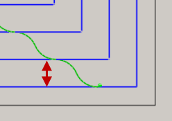
Smoothing
Smooths the toolpath by removing excessive points and fitting arcs where possible within the given filtering tolerance.
Smoothing Off

Smoothing On
Smoothing is used to reduce code size without sacrificing accuracy. Smoothing works by replacing collinear lines with one line and tangent arcs to replace multiple lines in curved areas.
The effects of smoothing can be dramatic. G-code file size may be reduced by as much as 50% or more. The machine will run faster and more smoothly and surface finish improves. The amount of code reduction depends on how well the toolpath lends itself to smoothing. Toolpaths that lay primarily in a major plane (XY, XZ, YZ), like parallel paths, filter well. Those that do not, such as 3D Scallop, are reduced less.
Smoothing tolerance:
Specifies the smoothing filter tolerance.
Smoothing works best when the tolerance (the accuracy with which the original linearized path is generated) is equal to or greater than the Smoothing (line arc fitting) tolerance.
Rest Machining
Use Rest Machining.
Rest Machining
Limits the operation to just remove material that a previous tool or operation could not remove.
Rest Machining ON
Rest Machining OFF
Rest material source:
Specifies the source from which the rest machining is to be calculated.
- From previous operation(s)
- From operation(s)
- From tool
- From file
- From solid(s)
- From setup stock
From setup stock
Union of all dependent operations
Union of all dependent operations.
Include all previous operations
Include all previous operations.
Resolution:
Specifies the rest material resolution.
Overlap:
This value specifies how much rest material you can ignore. Use this parameter to avoid undesired passes where there is little rest material.
Tool diameter:
Specifies the diameter of the rest material tool.
Corner radius:
Specifies the corner radius of the rest material tool.
Taper angle:
Specifies the rest material tool taper angle.
Shoulder length:
Specifies the rest material tool shoulder length.
File:
Specifies the rest material file.
Adjustment:
Selects the rest material adjustment for respectively ignoring or ensuring milling of small cusps.
- Use as computed
- Ignore cusps
- Machine cusps
Adjustment offset:
This parameter specifies the amount of stock to be ignored, or additionally removed, depending on the rest material Adjustment setting. The parameter is primarily used to avoid machining of minor rest material with the Ignore cusps setting.
Rest material operation
Rest material operation.
Rest material stock to leave
Specifies the rest material stock to leave.
Clearance Height
The Clearance height is the first height the tool rapids to on its way to the start of the tool path.
Clearance Height
- Retract height: incremental offset from the Retract Height.
- Feed height: incremental offset from the Feed Height.
- Top height: incremental offset from the Top Height.
- Bottom height: incremental offset from the Bottom Height.
- Model top: incremental offset from the Model Top.
- Model bottom: incremental offset from the Model Bottom.
- Stock top: incremental offset from the Stock Top.
- Stock bottom: incremental offset from the Stock Bottom.
- Selected contour(s): incremental offset from a Contour selected on the model.
- Selection: incremental offset from a Point (vertex), Edge or Face selected on the model.
- Origin (absolute): absolute offset from the Origin that is defined in either the Setup or in Tool Orientation within the specific operation.
Clearance height offset:
The Clearance height offset is applied and is relative to the Clearance height mode selection in the above drop-down list.
Retract Height
Retract height mode sets the height that the tool moves up to before the next cutting pass. Retract height mode should be set above the Feed height and Top. Retract height mode is used together with the subsequent offset to establish the height.
Retract Height
- Clearance height: incremental offset from the Clearance Height.
- Feed height: incremental offset from the Feed Height.
- Top height: incremental offset from the Top Height.
- Bottom height: incremental offset from the Bottom Height.
- Model top: incremental offset from the Model Top.
- Model bottom: incremental offset from the Model Bottom.
- Stock top: incremental offset from the Stock Top.
- Stock bottom: incremental offset from the Stock Bottom.
- Selected contour(s): incremental offset from a Contour selected on the model.
- Selection: incremental offset from a Point (vertex), Edge or Face selected on the model.
- Origin (absolute): absolute offset from the Origin that is defined in either the Setup or in Tool Orientation within the specific operation.
Retract height offset:
Retract height offset is applied and is relative to the Retract height mode selection in the above drop-down list.
Feed Height
Feed height mode set the height that the tool rapids to before changing to the feed/plunge rate to enter the part. Feed height mode should be set above the Top. A drilling operation uses this height as the initial feed height and the retract peck height. Feed height mode is used together with the subsequent offset to establish the height.
Feed Height
- Clearance height: incremental offset from the Clearance Height.
- Retract height: incremental offset from the Retract Height.
- Disabled: Disabling the Feed Height causes the tool to rapid down to the lead-in.
- Top height: incremental offset from the Top Height.
- Bottom height: incremental offset from the Bottom Height.
- Model top: incremental offset from the Model Top.
- Model bottom: incremental offset from the Model Bottom.
- Stock top: incremental offset from the Stock Top.
- Stock bottom: incremental offset from the Stock Bottom.
- Selected contour(s): incremental offset from a Contour selected on the model.
- Selection: incremental offset from a Point (vertex), Edge or Face selected on the model.
- Origin (absolute): absolute offset from the Origin that is defined in either the Setup or in Tool Orientation within the specific operation.
Feed height offset:
Feed height offset is applied and is relative to the Feed height mode selection in the above drop-down list.
Top Height
Top height mode sets the height that describes the top of the cut. Top height mode should be set above the Bottom. Top height mode is used together with the subsequent offset to establish the height.
Top Height
- Clearance height: incremental offset from the Clearance Height.
- Retract height: incremental offset from the Retract Height.
- Feed height: incremental offset from the Feed Height.
- Bottom height: incremental offset from the Bottom Height.
- Model top: incremental offset from the Model Top.
- Model bottom: incremental offset from the Model Bottom.
- Stock top: incremental offset from the Stock Top.
- Stock bottom: incremental offset from the Stock Bottom.
- Selected contour(s): incremental offset from a Contour selected on the model.
- Selection: incremental offset from a Point (vertex), Edge or Face selected on the model.
- Origin (absolute): absolute offset from the Origin that is defined in either the Setup or in Tool Orientation within the specific operation.
Top offset:
Top offset is applied and is relative to the Top height mode selection in the above drop-down list.
Bottom Height
Bottom height mode determines the final machining height/depth and the lowest depth that the tool descends into the stock. Bottom height mode needs to be set below the Top. Bottom height mode is used together with the subsequent offset to establish the height.
Bottom Height
- Clearance height: incremental offset from the Clearance Height.
- Retract height: incremental offset from the Retract Height.
- Feed height: incremental offset from the Feed Height.
- Top height: incremental offset from the Top Height.
- Model top: incremental offset from the Model Top.
- Model bottom: incremental offset from the Model Bottom.
- Stock top: incremental offset from the Stock Top.
- Stock bottom: incremental offset from the Stock Bottom.
- Selected contour(s): incremental offset from a Contour selected on the model.
- Selection: incremental offset from a Point (vertex), Edge or Face selected on the model.
- Origin (absolute): absolute offset from the Origin that is defined in either the Setup or in Tool Orientation within the specific operation.
- To chamfer width: allows the tool to drill just enough to make the chamfer width match the input parameter. The input parameter should not exceed the tool's chamfer width. The calculated height offset is dependent on the tool's parameters (diameter, tip diameter, and tip angle) and on the diameter of the hole. Acceptable selections include cylindrical faces, circles, or arcs.
- To chamfer diameter: the diameter of the new hole is equal to the input parameter. Therefore, the input parameter should not exceed the tool's diameter. The calculated height offset is dependent on the tool's parameters and independent of the hole selection. Acceptable selections include cylindrical faces, circles, or arcs.
Bottom offset:
Bottom offset is applied and is relative to the Bottom height mode selection in the above drop-down list.
Clearance
Specifies the cylindrical plane to which the tool retracts at the start and end of an operation. You can choose from the following cylindrical planes.
Clearance
- Stock OD
- Model OD
- Outer limit
- Inner limit
- Model ID
- Stock ID
- Selection
- Radius
- Diameter
Clearance offset:
Specifies the clearance offset value.
Outer Radius
Defines the radial confinement by limiting the outer radial range of the toolpath. You can choose from the following:
Outer Radius
- Stock OD
- Model OD
- Inner limit
- Model ID
- Stock ID
- Selection
- Radius
- Diameter
Outer radius offset:
Specifies the outer radius offset value.
Inner Radius
Defines the radial confinement by limiting the inner radial range of the toolpath. You can choose from the following:
Inner Radius
- Stock OD
- Model OD
- Outer limit
- Model ID
- Stock ID
- Selection
- Radius
- Diameter
Inner radius offset:
Specifies the inner radius offset value.
Tool...
Opens the Tool Library dialog box.
Finishing step
Specifies that a finishing step should be taken
Finishing step
From other side
Specifies that the toolpath starts on the other side of the part.
Unselected
Selected
Use chip thinning
Enable to use a roll-on cut to keep the chips thin.
Lift height:
Specifies the lift distance during repositioning moves.
Lift height 0
Lift height .1 in
No-engagement feedrate:
Specifies the feedrate used for movements where the tool is not in engagement on the material, but is also not retracted.
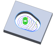
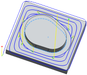
Use slot clearing
Enable this setting to start pocket clearing with a slot along its middle, before continuing with a spiral motion towards the pocket wall.
This feature can be used to reduce linking motion at corners for some pockets.
Use slot clearing enabled
Use slot clearing disabled
Slot clearing width:
The width of the initial clearing slot along the middle of the pocket before continuing with a spiral motion towards the pocket wall.
Slot clearing width
Compensation radius allowance:
This parameter specifies a range of tool diameters that can be safely used, instead of only the tool selected for the operation.
The allowed range of tool radii start from the selected tool radius and goes up to the selected tool radius, plus the given allowance.
Make sharp corners
Specifies that sharp corners must be forced.
Chamfer
Specifies that the contouring operation will be used to create a chamfer.
Geometry Selection Tips:
Sharp Corners
Sharp Corners - Select the sharp corner and define the size of the chamfer using the Chamfer Width setting.
Chamfered Edges
Chamfered Edges - Select the bottom edge of the chamfer. The chamfer width is calculated automatically.
Order by islands
Specifies the order in which depth cuts are taken when there are multiple profiles.
Disabled
Disabled - Depth cuts are ordered by depth.
Enabled
Enabled - Depth cuts are ordered by profile.
Allow stepover cusps
When programming flat faces with a tool that has a radius in the corner, a cusp (or scallop) can be produced between stepovers.
By default, the Maximum stepover value is overridden to insure that no stepover cusps are produced.
Allow stepover cusps disabled
Allow stepover cusps enabled
Above - Pocket machined with a 3/8" bullnose end mill @ 0.25" Max Stepover.
Machine straight on
Avoids machining along the steep areas by automatically choosing the best direction for the parallel passes.
Simple ordering
Enable to force simple ordering across the cutting direction instead of ordering by shortest distance. You can use this feature to avoid marks on the machined part in some cases. However, the machining time will be increased due to additional linking motion.
Stock offset:
Specifies the distance to offset the stock contour outwards.
Stock Offset
Stock offset:
Specifies the distance the machining boundary extends beyond the stock boundary in both X & Y.
Stock Offset
Lead end distance:
Specifies the distance the lead out feedrate begins before the end of the selected geometry.
@ 0 in.
@ .5 in.
Outer corner mode
When machining outer corners, it may be necessary to avoid rolling around the corner in order to leave the corner perfectly sharp.
The Outer corner mode setting lets you machine outer corners in three different ways.
- Roll around corner - keeps contact with the corner throughout the motion.
- Keep sharp corner - continues the toolpath to a single point corner, losing contact with the material temporarily.
- Keep sharp corner with loop - similar to Keep sharp corner, but also performs a horizontal lead-out and lead-in at the corner.
Preserve order
Specifies that features are machined in the order in which they were selected. When unselected, Inventor HSM optimizes the cut order.
Maximum angle (deg):
Specifies the maximum plunge angle for the passes.
Minimum angle:
The smallest angle (from the tool orientation Z-axis) of the holes to machine.
Maximum angle:
The largest angle (from the tool orientation Z-axis) of the holes to machine.
Minimum diameter:
The diameter of the smallest holes to machine.
Maximum diameter:
The diameter of the largest holes to machine.
Cutting mode:
The cutting mode specifies how to machine down the sides.
Single Pass
From Bottom
Trim from Bottom
From Top
Trim from Top
Spiral
Morph
Cutting mode:
The cutting mode specifies how to machine along the ISO parametric directions of selected surfaces.
- Trim impossible - Remove impossible tool path moves.
- Fail when impossible - Fail when impossible tool path moves are generated.
- Turn when impossible - Do a "turn" away from impossible tool path segments.
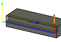
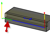
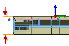
Stock Thickness
Specifies the overall thickness of the stock.
Stock Thickness
Tool offset:
Specifies an extra offset along the tool axis relative to the bottom guide curve.
Pass overlap:
Specifies the distance to extend machining for a closed pass.
Maximum fan distance:
Specifies the maximum distance over which to fan the tool axis.
Tangential fragment extension distance:
Specifies the tangential extension of the passes.
Tool clearance:
Specifies an additional tool clearance angle.
Machine inside
Enable to specify that the operation should machine the ID of the workpiece.
Machine inside disabled
Machine inside enabled
Use tailstock
A tailstock is used to apply support to the longitudinal rotary axis of the workpiece being machined. This is particularly useful when the workpiece is relatively long and slender. Failing to use a tailstock can cause the workpiece to bend excessively while being cut and cause "chatter".
Use part catcher
Enable to activate part catcher when available.
Go home:
Specifies the home positioning at the beginning and end of the toolpath. The four options are self-explanatory.
- Don't go home
- Go home at beginning
- Go home at end
- Go home at beginning and end
Mode:
Depending on the turning strategy, this setting determines whether the tool machines axially or radially as well as the approach/retract direction.
- Outside grooving - The tool approaches from/retracts to the outside and machines axially.
- Inside grooving - The tool approaches from/retracts to the centerline and machines axially.
Confinement
Turning operations attempt to remove all the remaining stock possible with the selected operation type. Toolpaths can be contained within a specific region using the Confinement button to select confinement boundaries. Confinement regions can be defined with a combination of edges, surfaces, or sketch points.
Frontside stock offset:
Specifies the distance to machine beyond the frontside of the model.
Backside stock offset:
Specifies the distance to machine beyond the backside of the model.
Thread faces
Selection button for faces to be threaded.
Apply back from front
Enable to
Groove side alignment:
- Back - Offsets the tool from the selected groove geometry in the negative Z direction (toward the backside of the stock).
- Middle - Centers the tool on the selected groove geometry.
- Front - Offsets the tool from the selected groove geometry in the positive Z direction (toward the frontside of the stock).
Groove tip alignment:
- Cut-through - The tool tip extends past the selected radial distance in the negative radial direction for outside grooving, and in the positive radial direction for inside grooving. Important: The choice between inside/outside grooving appears on the Tool tab - not the Geometry tab.
- Tip - The tool tip stops at the selected radial distance.
Roughing overlap:
Specifies the radial overlap of the roughing passes.
Allow grooving
Linear lead-in angle:
Specifies the lead-in direction.
Lead-in extension:
Specifies the lead-in extension.
Linear lead-out angle:
Specifies the lead-out direction.
Lead-out extension:
Specifies the lead-out extension.
Lead to center
Specifies that the lead in/out movement should be into the center of the geometry.
Maximum grooving stepover:
Specifies the maximum grooving stepover.
Grooving pattern:
There are three grooving pattern options:
- Full stepdown -
- Partial stepdown -
- Sideways with partial stepdown -
Backoff distance:
Specifies the distance to back off from the stock before retracting.
Transfer stock
Use pecking
Enable to activate pecking options.
Pecking depth:
Specifies the pecking depth.
Pecking retract:
Specifies the pecking retract amount.
Use reduced feedrate
Enable to reduce the feed when grooving or parting.
Reduced parting feed radius:
Specifies the radius at which to reduce the feedrate when parting.
Reduced feed:
Specifies the reduced feedrate to be used at corners.
Feed Optimization
Specifies that the feed should be reduced at corners.
Maximum directional change:
Specifies the maximum angular change allowed before the feedrate is reduced.
Reduced feed radius:
Specifies the minimum radius allowed before the feed is reduced.
Reduced feed distance:
Specifies the distance to reduce the feed before a corner.
Reduced feedrate:
Specifies the reduced feedrate to be used at corners.
Only inner corners
Only reduce the feedrate on inner corners.
Both ways
Specifies that the operation uses both Climb and Conventional milling to machine open profiles.
Unselected
Selected
Pitch diameter offset:
Creates a positive or negative diameter offset from the selected geometry.
Threading hand:
- Right handed
- Left handed
Thread depth:
Specifies the thread depth.
Thread pitch:
Specifies the thread pitch.
Do multiple threads
Enable to activate the number of threads.
Number of threads:
Specifies the number of threads.
Infeed mode:
The infeed is the depth of cut per pass and is critical in threading. Each successive pass engages a larger portion of the cutting edge of the insert. There are two infeed mode options.
- Constant infeed - With this option, the cutting force and metal removal rate can increase dramatically from one pass to the next. Example: When producing a 60 degree thread form using a constant 0.010 inch infeed per pass, the second pass removes three times the amount of metal as the first pass. The amount of metal removed continues to grow exponentially with each subsequent pass.
- Reduced infeed - This option maintains more realistic cutting forces and reduces the depth of cut with each pass. Because it avoids the increased metal removal rate of constant infeed, it is the recommended setting.
Infeed angle:
Specifies the infeed angle.
Fade thread end
Enable to fade out the thread at the end.
Spring pass
Enable to perform the final finishing pass twice to remove stock left due to tool deflection.
Use cycle
Enable to
Stock in chuck:
Specifies the amount of stock in the chuck.
Eject stock:
Specifies the amount of stock to eject from the current chuck.
Finish feedrate:
The feedrate used for the final finishing pass.
Tangential extension distance:
Specifies the distance to extend the open contours tangentially.
No Tangential extension
10 mm Tangential extension
Separate tangential end extension
Specifies the distance to extend the open contours tangentially at the end.
Linear lead length:
Specifies the length of the linear leads.
Number of steps:
Specifies the number of radial steps.
Setup type
Specifies the machining method.
Milling
Milling - Use Milling when processing toolpaths for a mill regardless of configuration.
Turning
Turning or mill/turn - Use Turning when processing toolpaths for a lathe, including lathes with live tooling and mill/turn configurations.
Scale
Specifies the scale of the model.
Stock Definition
Automatic
Automatic - Creates a cubic stock body that is larger than the model by given offset values.
Cylindrical
Cylindrical - Creates a cylindrical stock body around a defined axis.
From Solid
From Solid - Gives complete control over stock definition by using a solid body in a multi-body part, or from a part file in an assembly.
From Extruded Sketch
From Extruded Sketch - Creates a stock body from a sketch.
Reverse direction
Specifies which direction of the extrusion from sketch to be reversed.
Stock offset mode
Specifies how stock is added to the model.
No Additional Stock
No Additional Stock - No offset values are added to the stock size.
Add Stock to Sides and Top-Bottom
Add Stock to Sides and Top-Bottom - Symmetrical stock offset for all sides. Unique values for top and bottom offsets.
Add Stock to All Sides
Add Stock to All Sides - Unique values for all offset directions.
Stock side offset:
Specifies the additional stock on the sides.
Stock top offset:
Specifies the additional stock on the top.
Stock bottom offset:
Specifies the additional stock on the bottom.
Stock +X offset:
Specifies the offset of the stock.
Stock -X offset:
Specifies the offset of the stock.
Stock +Y offset:
Specifies the offset of the stock.
Stock -Y offset:
Specifies the offset of the stock.
Stock +Z offset:
Specifies the offset of the stock.
Stock -Z offset:
Specifies the offset of the stock.
Use stock radius
Specifies the radius of cylindrical stock instead of using an offset value.
Stock radius:
Specifies the radius of the stock.
Radial stock offset:
Specifies the radial offset of the stock.
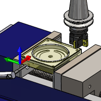
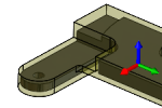
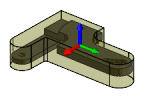
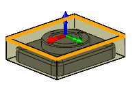
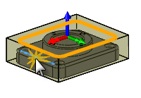
WCS origin
Specifies the location of the Work Coordinate System (datum) for the setup relative to the stock.
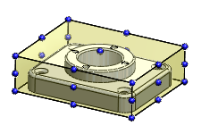
WCS Origin Selection
The orientation of the WCS above is defined with the WCS orientation selection box.
Home position
Specifies the home position along Z.
WCS offset
Identifies the desired workpiece coordinate system (WCS) for the setup. It is the responsibility of the post processor configuration to map this number to the actual WCS on the machine.
Work duplicates
Specifies the number of workpiece duplicates. This is the total number of instances.
WCS offset increment
Specifies the work offset increment used for workpiece duplication.
Operation order
Specifies the ordering of the individual operations.
Stock Contours
Specifies the perimeter of the stock that needs to be faced.
Disabled
Disabled - The perimeter of the stock as defined in the setup is used.
Enabled
Enabled - Selected faces or edges are projected to the model top.
Comparison Tolerance
Used when comparing if two entities are the same, e.g. if two holes have the same diameter.
Advanced parameter. Only shown when advanced mode is enabled
Spindle Shift Orientation
The spindle orientation to use when shifting during boring. Note that not all CNC controls have full support for controlling the spindle orientation.
Fast 3D Mode
The fastest simulation mode. Simulation is done to a limited resolution controlled by the quality slider. This mode is only available when simulating 3-axis milling operations in the same tool orientation. Undercutting cannot be simulated for this mode.
Solid Mode
This is the most flexible mode. The stock quality is better than the Fast 3D Mode but done to a tolerance controlled by the quality slider. This mode gives the best results for turning and supports multi-core/CPU for fast simulation.
High Quality Mode
The High Quality Mode can, in some cases, provide better visualization of the stock and can also be faster to update than the other modes. However, the stock has to be updated whenever you zoom and rotate in the model viewport.
Fast Mode
The Fast Mode often provides good results for a milling toolpath. It also supports multi-core/CPU for fast simulation and often provides a result faster than possible with Solid Mode. For turning, you should still select the Solid Mode.
Number
The number used to select the tool on the CNC machine.
Length Offset
The index of the tool length offset. This parameter is normally set when using tools with multiple tips indexed by length.
Diameter Offset
The index of the tool diameter offset.
Compensation Offset
The index of the tool compensation offset used for turning.
Manual Tool Change
Enable to force a manual tool change on machines with an automatic tool changer.
Break Control
Enable to check for tool breakage after use.
Coolant:
The type of coolant used with the tool.
Material
The tool material.
Description
A textual description of the tool. This description is included in the tool name shown throughout Inventor HSM.
Comment
A textual comment for the tool. The comment is typically included in the post-processed output.
Vendor
The vendor of the tool. Use this to identify the specific tool used.
Product ID
The vendors' identifier (ID) for the tool. Use this to identify the specific tool used.
Type
The type of the tool.
Unit
The tool unit.
Diameter
The diameter of the cutter.
Tip Diameter
The tip diameter of the cutter.
Corner Radius
The corner radius of the cutter.
Taper Angle
The taper angle.
Tip Angle
The angle of the tool tip. This angle is used to calculate the extra depth needed to break the tool through the material.
Flute Length
The tool flute length.
Shoulder Length
The tool shoulder length.
Body Length
The tool body length.
Shaft Diameter
The tool shaft/arbor diameter.
Thread Pitch
The pitch of the tap thread, specified as the vertical distance between the teeth of the tap.
Use constant surface speed
Enable to automatically adjust the spindle speed to maintain a constant surface speed between the tool and the workpiece as the cutting diameter changes . Constant Surface Speed (CSS) is specified using G96 on most machines.
Spindle speed:
The rotational speed of the spindle.
Stock diameter:
The diameter of the turning stock.
Surface speed:
The spindle speed expressed as the speed of the tool on the surface.
Ramp spindle speed:
The rotational speed of the spindle when performing ramp movements.
Number of flutes:
The number of cutting flutes on the tool.
Use feed per revolution
Enable to automatically adjust the feedrate based on the RPM of the spindle to maintain a constant chip speed.
Cutting feedrate:
Feed used in cutting moves.
Feed per tooth:
The cutting feedrate expressed as the feed per tooth.
Lead-in feedrate:
Feed used when leading in to a cutting move.
Lead-out feedrate:
Feed used when leading out from a cutting move.
Ramp feedrate:
Feed used when doing helical ramps into stock.
Plunge feedrate:
Feed used when plunging into stock.
Feed per revolution:
The plunge feedrate expressed as the feed per revolution.
Retract feedrate:
Feed used when retracting and not using rapid (G0) moves.
Chamfer extension:
Distance by which to extend the chamfer cutting pass.
Chamfer angle:
The angle of the chamfer measured from the Z-axis.
Tangential end extension distance:
Specifies the distance to extend the open contours tangentially at the end.
Order by step
When enabled, each roughing and finishing step is machined to the full depth before moving to the next step.
Order by step disabled
Order by step enabled
Shaft & Holder
When using a tool with a holder, you can choose between one of five different shaft and holder modes, depending on the machining strategy. Collision handling can be done for both the tool shaft and holder, and they can be given separate clearances.
- Disabled - Ignores any shaft/holder collisions.
Disabled
- Pull away - The toolpath pulls away from the workpiece to maintain a safe distance between the shaft and/or holder.
Pull away
- Trimmed - Sections of the toolpath that result in safe distances between the shaft and/or holder being violated are trimmed away.
Trimmed
- Detect tool length - The tool is automatically extended further out of the holder to maintain the specified safe distance between the shaft and/or holder and the workpiece. A message indicating how the far the tool is extended out of the holder is logged.
Detect tool length
- Fail on collision - The toolpath calculation is aborted and an error message logged when the safe distance is violated.
Use shaft
Specifies that the shaft of the selected tool will be used in the toolpath calculation to avoid collisions.
Shaft clearance:
The tool shaft always stays this distance from the part.
Use holder
Specifies that the holder of the selected tool will be used in the toolpath calculation to avoid collisions.
Holder clearance:
The tool holder always stays this distance from the part.
Holder
When using a tool with a holder, you can choose between three different holder modes. Collision handling can be done for the tool holder, and they can be given separate clearances.
- Disabled - Ignores any shaft/holder collisions.
Disabled
- Pull away - The toolpath pulls away from the workpiece to maintain a safe distance between the shaft and/or holder.
Pull away
- Fail on collision - The toolpath calculation is aborted and an error message logged when the safe distance is violated.
Cusp height
Cusp height is the theoretical surface finish produced by successive toolpaths left by the radius of the cutter. A smaller tool diameter or a larger stepover produces a larger cusp height.
Cusp height
Machine steep areas
Specifies that extra passes will be added where the surface is steep perpendicular to the machining direction. This is important for plastic injection molds where the cutting direction needs to be consistent to avoid marks on the parts.
Disabled

Enabled
Minimum steep stepover:
Defines the minimum stepover that is used when Machine steep areas is enabled, regardless of the stepdown amount.
Maximum steep stepdown:
Defines the maximum steep stepdown.
Add perpendicular passes
Enable to add a set of passes perpendicular to the specified machining direction to reduce machining cusps.
Disabled
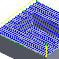
Enabled
Spiral mode:
- Spiral - creates a path that spirals out from the center point until it reaches the containment boundary or max radius.
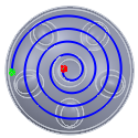
Spiral
- Spiral with circles - adds a circular toolpath at the minimum radius and at the maximum radius. The circular toolpath is only added if the minimum radius is larger than 0 and the maximum radius is smaller than the radius of the containment boundary.
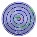
Spiral with circles
- Concentric circles - produces concentric circle paths that are linked. The resulting paths form a circular pattern rather than a spiral pattern.
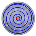
Concentric circles
- Morphed spiral - Spirals from a shape that is not round.
Use morphed spiral machining
Enable to create a constant spiral move toolpath for the pocket. This can provide a smooth run on the machine.
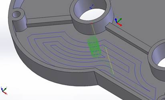
Standard 2D pocket toolpath
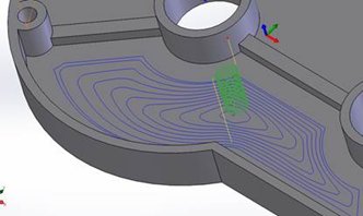
Morphed spiral 2D pocket toolpath
Fillets
Enable to enter a fillet radius.
Fillet radius:
Specify a fillet radius.
Machine areas using boundaries
When enabled, passes are generated from the confinement boundaries defined by all confinement features (machining boundaries, slope, heights, etc.). When disabled, passes are generated from the machining boundaries resulting in passes normally not following the surface.
Boundary overlap:
When using slope confinement and/or rest machining for a Scallop operation, you can enable the Machine areas using boundaries check box to start offsetting the toolpath from the boundaries created by the slope and/or rest material detection.
You can specify a boundary overlap so that the boundary of the detected slope range or rest area is extended by the specified overlap amount.
Order bottom-up
Contour passes are usually ordered from top to bottom. Enable this check box to specify that passes should be ordered bottom-up (bottom to top).
Ordering is done so that the passes with the smallest Z-level tool orientation are done first in one operation for multiple contours. This method is very useful for machining fragile materials like graphite.
Contour offset:
This value is used to offset the center of the tool from the generated toolpath by a specified distance.
Morph mode:
- Simple - Linear interpolation between points.
- Closest - End-point-to-end-point.
- Automatic - Automatic morph between points.
Use stepover
Enable to automatically add stepovers as needed.
Number of offset stepovers:
The number of offset stepovers to use for the morph operation.
Number of stepovers:
The number of roughing steps.
Up/down direction:
- Up and down -
- Only down -
- Only up -
Pass overlap:
Specifies the overlap distance used for passes split due to up/down machining.
Number of stepovers:
The number of additional steps to each side of the pencil seed.
Isometric direction:
Specifies whether to do the flow Along u (similar to the X-axis in the Cartesian coordinate system) or to flow Along v (similar to the Y-axis in the Cartesian coordinate system).
- Along u
- Along v
Use multi-axis
Specifies that the tool should follow the surface normals.
Multi-Axis Tilting
Enables multi-axis tilt to avoid collision with the holder when using short tools.
Forward tilt:
Specifies the number of degrees the tool should be tilted forward.
Sideways tilt:
Specifies the number of degrees the tool should be tilted sideways.
Minimum tilt:
Specifies the minimum allowed tilt from the selected operation tool axis.
Maximum tilt:
Specifies the maximum allowed tilt from the selected operation tool axis.
Maximum fan distance:
Specifies the maximum distance over which to fan the tool axis.
Maximum segment length:
Specifies the maximum length of a single segment for the generated toolpath.
Maximum tool axis sweep:
Specifies the maximum angle change in a single tool axis sweep for the generated toolpath.
Tabs
You can add tabs to the 2D Contour toolpath to hold the workpiece securely while all other material is machined away. Tabs are very useful when cutting thin plastic or wood materials using 2D routers.
- Shape - Choose between Rectangular or Triangular shaped tabs.
- Width - Specify a value for the tab width.
- Height - Specify a value for the tab height.
- Positioning - You can choose to specify the distance between tabs with an explicit numeric value (By distance), or pick points along the contour path to indicate the desired tab positions (At points).
- Distance - Specify a value for the distance between tabs.
- Positions - Use your cursor to select points along the contour path for the tab locations.
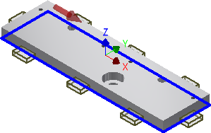
Rectangular tabs
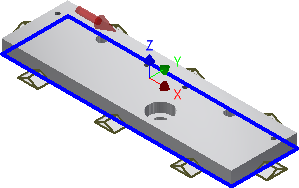
Triangular tabs