Next we need to machine the central groove and to clean the corners/angles. This is because the previous operation left material in these areas due to the corner radius of the insert used. It is possible to do both tasks in a single operation using the Groove strategy to remove the excess material.
- On the ribbon, click
CAM tab
 Turning panel
Groove
Turning panel
Groove
 .
.
 Tool tab
- On the Tool tab, click
 to open the Tool Library.
 - Click the
 button to add a new tool.
 - On the Insert tab, select Grooving from the Type: drop-down menu. Then, select Square from the Shape: drop-down menu to specify the tool tip and enter the following values:
- Corner radius: 0.25 mm
- Groove width: 2.5 mm
- Width: 2.2 mm
Leave the rest of the values at their defaults.
- On the Holder tab, select External Grooving from the Style: drop-down menu.
- Change Head length to: 50 mm
- On the Setup tab, select Insert Center from the Compensation: drop-down menu.
- Click the
 button to select the tool for your operation and close the tool dialog. This same tool will be used for a later parting operation.
 - Click
 to close the Tool Library dialog.
 Geometry tab
Now remove the material the previous operation did not remove.
- Click the Geometry tab.
- Enable the Rest Machining group.
 Passes tab
The parameters in the Passes group control how the grooving toolpath is calculated.
- Click the Passes tab.
- Enable the Finishing passes check box.
- Enable the Roughing Passes group.
Start the Calculation
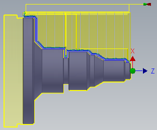
- Click at the bottom of the Operation dialog box, or right-click in the graphics window and select OK from the marking menu, to automatically start calculating the toolpath.
The toolpath is now calculated and a preview appears in the graphics window.
Continue to To Cut an External Thread...