These options appear as a subset of the Tubes section in the Paint Effects Brush Settings window, and the Attribute Editor for any brush node.
These settings define how tubes are initially created.
- Tubes Per Step
-
Defines the number of new tubes that are planted at each step in the growth simulation (each time Paint Effects samples a new point along the stroke path). The tubes are planted along the stroke path segment between the two sample points defining the step.
 Tip: If you are painting in the Paint Effects panel (canvas or scene painting view) with a brush that has tubes. You can adjust the Tubes Per Step setting from the toolbar by changing the number in the TS box.
 - Tube Rand
-
Randomizes the position of tubes along the path. The lower the value, the more orderly the tubes appear. This attribute does not randomize emitter positions.
- Start Tubes
-
Defines the number of tubes that are planted at the first point of each path you draw. If you set Tubes Per Step to 0, you can use this setting to create a single object along the path. For example, set Tubes Per Step to 1 to form the trunk of only a single tree for every stroke, or set it to 100 to create a sunrise or spot glow effect.
- Segments
-
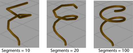
Defines the maximum number of segments a tube can have. Since tubes each grow one segment during each step in the growth simulation, the number of segments defines the “life span” of the tube. If you increase Segments, the tube length remains the same, but the segments making up each tube become smaller. Segments are straight, therefore more segments make the tubes appear smoother and less jointed.
- Length Min, Length Max
-
These settings define the range of possible lengths for tubes (when they have completed growing). Paint Effects will create tubes with random lengths between the Length Min and Length Max values. If Tube Completion is off, the tubes may not reach the Min or Max values.
- Tube Width 1, Tube Width 2
-
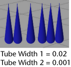
These settings define the width of the tubes at the base (Width 1) and at the tip (Width 2). The tube width changes linearly between these two values.
See also Width Rand and Width Bias below, and Width Length Map in the Length Mappings brush settings section of Paint Effects Brush Settings.
- Width Rand
-
Randomizes the width of tubes along the stroke path. If the value is 0, all tubes will be the width specified by Tube Width 1 and Tube Width 2. The higher the value, the larger variation there is between the Tube Width values.

- Width Bias
-
This setting is used only when Width Rand is greater than 0. It defines how the random widths are distributed. If Width Bias is 0, then there will be just as many wider tubes as there are thinner tubes. If Width Bias is a positive value, then there will be more wider tubes created than thinner ones. If Width Bias is a negative value, then there will be more thinner tubes created than wider ones. If you are creating plants, negative values give the most realistic results. (For each larger plant, there are usually a number of smaller plants.)

- Segment Length Bias
-
Defines how segments are distributed by length. If Segment Length Bias is 0, all tube segments are the same length. If the value is positive, segments closer to the base are longer. If the value is negative, segments closer to the tip are longer. The value represents the proportion of segments that are longer.
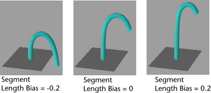
If Length Flex in the Forces section () is set to 1, the segments are infinitely stretchy, therefore this setting has no effect (see Forces brush settings).
- Segment Width Bias
-
Defines how segment width affects segment length. If Segment Width Bias is 0, width of a segment has no effect on its length. If the value is positive, wider segments are longer. If the value is negative, wider segments are shorter.
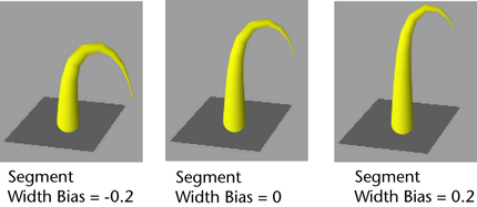
- Surface Snap
-
When on, the start position of tubes snap to the closest point on the geometry surface. Surface Snap works best on non-deforming geometry.
Width Scale
- Selected Position, Selected Value, and Interpolation
-
These settings allows you to use a graph to control the width from base to tip of tubes, rather than using a simple linear interpolation between two values. When combined with the Mesh Brush Type you can define shapes like spheres, as well as control the profile of a tube. Width Scale is applied as a scale to the current width and defaults to 1.0 so that previous presets work with it.

Tube Direction
Select what you want the primary axis to be to generate tubes.
- Along Normal
-
Tubes are generated along the surface normal or the normal defined for the stroke. See Use Normal in the Normal Direction section of strokeShape node).
Tip: You can set a hotkey to flip the surface normal when you paint strokes (ToggleOppositeFlagOfSelectedShapes). For details, see Reverse surface normals on painted objects. - Along Path
-
Tubes are generated along the path of the stroke (tangent to the stroke path curve).

- Elevation Min, Elevation Max
-
Imagine you are standing on a paint path, pointing straight ahead in the direction of the path. Moving your pointing hand straight up and down is like changing the elevation of your arm. These attributes define the range of possible elevations for tubes to lie. When both values are 1, tubes stand straight up (90 degrees, normal to the surface). When both values are 0, tubes lie flat along the path (0 degrees, tangent to the surface). When both values are 2, tubes lie flat along the path opposite to the path direction (180 degrees, tangent to the surface).
Elevation is the same as Inclination in Maya Fur.

- Azimuth Min, Azimuth Max
-
As with Elevation, imagine standing on the paint path, pointing straight ahead in the direction of the path. Rotating your body left and right is like changing the azimuth of your arm. These attributes define the range of possible angles for tubes to rotate around the normal axis. When both values are 0, tubes point along the path direction. If both Elevation Min and Elevation Max are 1, Azimuth values have no effect.
Azimuth is the same as Polar in Maya Fur.

Simplify Method
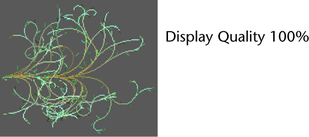
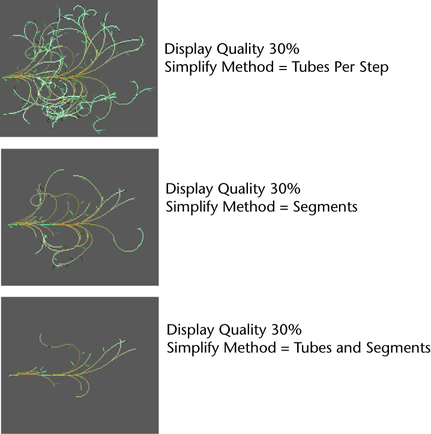
You can simplify the wireframe display of a stroke by decreasing the display quality. Use this option to select what aspect of the stroke you want the display quality to affect. Display Quality does not affect the rendered strokes—only the quality of the wireframe representation.
- Tubes Per Step
-
The display quality only affects the number of tubes.
- Segments
-
The display quality only affects the number of segments along the tubes.
- Tubes and Segments
-
The display quality affects the number of tubes and the number of segments.
