To mathematically solve the FEA solution, it is necessary to construct the mesh. The mesh is composed of small pieces called elements; at the corner of each element is a node. The type of mesh depends on the property definition.
A collection of settings provides control over the element size, element order, and local refinement. Because the solution accuracy is so dependant on the fidelity of the mesh, it is important to take the time to define a high quality mesh for your simulations.
Element Types and Their Properties
There are three types of elements supported in Autodesk® Nastran® In-CAD:
- Sold Elements
- Shell Elements
- Line Elements
The following sections introduce these three element types and describe their properties.
Solid Elements
When using solid elements, the geometry is entirely described by the CAD model geometry. Tetrahedrons are the element type for three dimensional, solid meshes. There are two types of tetrahedrons:
- Linear Tetrahedrons: These have 4 nodes, and are mathematically stiff. It is best to use these only for trend studies where absolute results are not as important as relative changes.
- Parabolic Tetrahedrons: These have 10 nodes, and are excellent general purpose elements suitable for most applications.


Shell Elements
Autodesk Nastran In-CAD can mesh shells with triangles and quadrilaterals using these element types:
|
Element Type |
Number of Nodes |
|---|---|
|
Linear Tri |
3 Nodes |
|
Parabolic Tri |
6 Nodes |
|
Linear Quad |
4 Nodes |
|
Parabolic Quad |
8 Nodes |
Note that linear shells are recommended for most analyses. The preferred element is CQUARD/CTRIAR. This includes a "Drilling DOF."
The primary property of shell elements is the thickness, t. You can assign the property to geometric surfaces or to the faces of geometric solids.
Line (Beam) Elements
There are three types of line elements supported by Autodesk® Nastran® In-CAD:
- Bar
- Beam
- Pipe
To define the geometry or cross-section for a beam element requires several properties. To input Property data, you can manually assign values on the Physical Property dialog. To define Cross Section settings, it is recommended to use the Element Library. By using the libraries, you can create PBEAML and PBARL elements which perform a maximum stress computation. This is unique to Autodesk Nastran. Additionally, using libraries allows you to save individual cross-sections for reuse.
Element Degrees of Freedom
Element degrees of freedom (DOF) link the mesh, element properties, and boundary conditions. It is important to note that nodes can only carry the loads they need to. For each element type, these are the degrees of freedom that nodes can carry:
- 3D Solids: 3 DOF (TX, TY, TZ)
- 3D Plates: 6 DOF (TX, TY, TZ, RX, RY, RZ)
- 2D Plates: 3 DOF (TX, TY, RZ)
- 3D Beams: 6 DOF (TX, TY, TZ, RX, RY, RZ)
Note that adjoining elements of similar type cancel out the rotational DOF's at the interface. It is recommended to use "sacrificial" element or rigid connectors to tie together dissimilar elements.
Mesh Settings
As mentioned above, it is very important to use a mesh that accurately represents the geometry and the physics you are simulating. A poorly defined mesh may produce results, but the accuracy of those results may be less than you need to make informed design decisions. The settings described in this section can be used to define a mesh to suit the analysis needs of your model.
Basic Settings
To access the Mesh Settings dialog from the ribbon, click the Global command from the Mesh group in the ribbon. Here is a summary of the command on the Mesh dialog:
- Global Element Size: All faces are meshed with this nominal dimension unless curvature settings override it.
- Element Order: Choose either Linear or Parabolic for all elements in the model.
- Mesh Table (button): Open the Mesh Table for controlling element attributes for each part in the model.
- Continuous Meshing: When checked, the mesher attempts to define compatible (matching) meshes on touching edges. This provides a higher level of load continuity than possible with the Welded Contact.
- Update: Create the mesh with the prescribed settings.
Advanced Settings
Click the Settings button on the Mesh dialog to open the Advanced Mesh Settings dialog. Note that it is a good idea to use the default settings unless you have a good understanding of the impact of different tolerances for your model. These are the settings that are most often adjusted:
- Max Element Growth Rate: Reducing this value extends the region in which smaller elements transition to larger elements. This can help to smooth the mesh in high stress gradients areas.
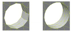
- Project Midside Nodes: This maps midside nodes of parabolic elements to the geometry. This is particularly helpful in areas of high curvature. The mesh on the left was created with this option disabled. The mesh on the right is with the option enabled:

Mesh Control Options
To refine the mesh locally, right-click on Mesh Model in the Model Tree, and select Add Mesh Control. You can apply mesh control for local mesh sizing on points, edges, and faces. You can control the mesh definition on edges either by specifying the number of elements or by the element size.
The mesh on the left has no local mesh control. The mesh in the middle has edge mesh control, and the mesh on the right has vertex mesh control:

Mesh Table
To control the element size, order, and specify advanced settings for the each part in the assembly, use the Mesh Table. To open the table, either click the Table button on the Mesh dialog or click Table from the Mesh panel in the ribbon.

With the check boxes (marked as "A"), you can mesh individual or selected parts. This is a very useful tool for locating meshing issues in assemblies.
The Importance of the Mesh on Convergence
In general, a higher element count leads to greater solution accuracy. This is because more nodes are available for calculating the response and because smaller elements minimize errors due to discretization. The practical limit to the effect of the mesh on the solution accuracy occurs when a mesh-independent solution is attained. This means that the solution does not change, regardless of further reductions in element size.
You can control the mesh to lead to convergence by reducing the element size locally and globally and by monitoring the changes in results. Models will converge with fewer second order elements (Parabolic Tetrahrons, for example) than with linear elements. This is because a single second order element can capture a more complex strain field than a linear element. However, the cost associated with second order elements is that they typically take longer to solve due to the higher node count.
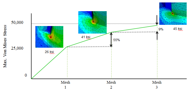
In the following, we see the effect of refining the mesh on the von Mises stress at a stress concentration point. As the mesh is refined from Mesh 1 to Mesh 3, we see a reduction in the amount of change in the stress at the point of interest. This means that the finer mesh is close to a mesh-independent solution, and smaller changes in the solution will occur as the mesh is further refined:

Note, however, when using shell and beam elements, it is best to use linear element types.
Reviewing Mesh Quality
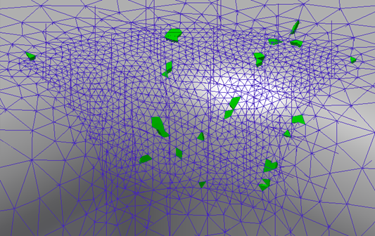
To determine if there are sub-optimal elements in the areas of interest (where stress is a significant concern), use the Check Mesh Quality tool. Open this by right-clicking on the Mesh Model branch of the Model Tree, and clicking Check Quality for all Meshes.
This tool performs an analysis of the mesh, and identifies areas that may need further refinement:

The Finite Elements in Autodesk Nastran In-CAD topic contains additional information about meshing.
|
Previous Topic: Modify Boundary Conditions Exercise |
Next Topic: Refine the Mesh Exercise |