Use settings in the Energy Model section of the Energy Settings dialog to determine how the energy analytical model is created using conceptual masses, building elements, or both.
These settings do not affect room-based or space-based gbXML export or heating and cooling loads in Revit MEP.
To open the Energy Settings dialog, click Analyze tab Energy Analysis panel
 (Energy Settings).
The following parameters are listed under the Energy Model heading.
Analysis Mode
Select the analysis mode to use for an energy simulation:
- Use Building Elements . (default) Create an energy model using building elements in the model (walls, floors, roofs, windows, rooms, spaces, and so on). If the model contains conceptual masses, they are ignored for the purposes of the energy simulation.
- Use Conceptual Masses . Create an energy model using the conceptual masses in the model. In order to be included in the analysis, the conceptual masses must contain mass floors. If the model contains building elements, they are ignored for the purposes of the energy simulation.
- Use Conceptual Masses and Building Elements . Create an energy model that is based on both conceptual masses and building elements in the model. In order to be included in the analysis, the conceptual masses must contain mass floors.
For all analysis modes, if the model includes a conceptual mass that does not contain mass floors, the mass is treated as a shading object. See Best Practices: Energy Analysis.
Analytical Space Resolution
Specify the size of the largest gap (between 2 Revit elements) through which analytic spaces will not "leak."
If you run an energy simulation and a message displays that the model is too large, increase this setting and rerun the energy simulation.
The default is 18 inches (457.2 mm). The minimum value is 6 inches (152.4 mm). The maximum value is 10 feet (3048 mm).
Analytical Surface Resolution
This setting specifies, in combination with the Analytical Space Resolution, how accurately the boundaries of analytic surfaces match the ideal boundaries. In general, reducing the Analytical Surface Resolution results in analytic surfaces with more accurate boundaries, but this also limits how accurately analytic surfaces are modeled.
If you run an energy simulation and a message displays that the model is too large, increase this setting and rerun the energy simulation.
The default is 12 inches (304.8 mm). The minimum value is 3 inches (76.2 mm). The maximum value is 10 feet (3048 mm).
Core Offset
Specify the distance to measure inward from the exterior walls to define the core zone.
The core of a building has heating and cooling loads that differ from the perimeter because it is not directly exposed to external weather conditions or daylight through windows. A typical core offset is 12-15 feet (4-5 m).
The core offset is used to perform automatic thermal zoning. See About Automatic Thermal Zoning.
Divide Perimeter Zones
Select this option to divide the perimeter of the building (excluding the core) into thermal zones.
Perimeter zones result in more accurate energy consumption estimates. For example, in the late summer afternoons, a west façade may encounter solar heat gain while the east façade does not. Perimeter zoning allows energy analysis of these perimeters to be handled separately.
Perimeter zones are required to perform automatic thermal zoning. See About Automatic Thermal Zoning.
When Analysis Mode is set to Use Conceptual Masses and Building Elements (recommended), the perimeter is divided into thermal zones using advanced algorithms for more accurate energy simulations.
When Analysis Mode is set to Use Conceptual Masses, the perimeter is divided into 4 simple thermal zones: northeast, southeast, northwest, and southwest.
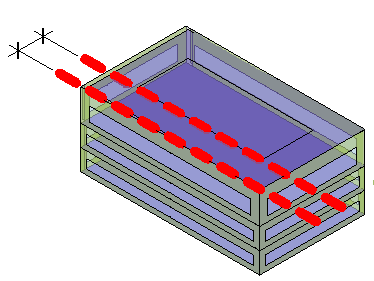
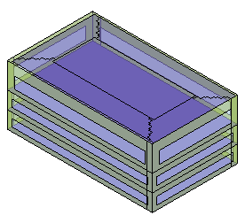
| A mass model with perimeter zones | A mass model with a core offset and perimeter zones |
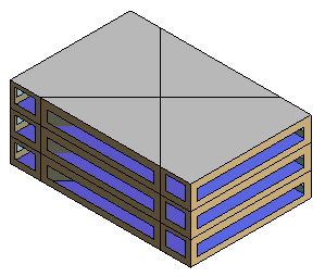 |
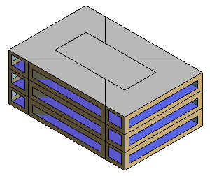 |
Conceptual Constructions
This setting specifies the constructions to use for different types of mass surfaces.
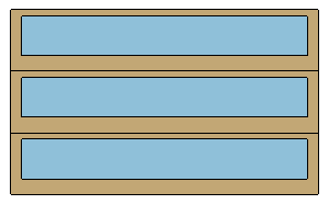
Target Percentage Glazing
This setting specifies the percentage of exterior walls to be glazed openings (windows). It is also known as the window-to-wall ratio (WWR). The default is 40%. For curtain walls, the maximum is 95%, which takes into account the framing area.
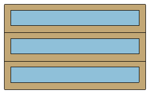
| Target Percentage Glazing = 40% | Target Percentage Glazing = 60% |
 |
 |
Target Sill Height
Specify the distance from the floor to the bottom of the window. Window areas below task height (typically 0.75 meters or 2.5 feet) contribute to heat gain and heat loss without contributing to effective daylighting.
The Target Percentage Glazing and Target Sill Height settings work together. If you specify a larger Target Percentage Glazing, Revit may use a sill height that is lower than specified to meet the requirement.
| Target Percentage Glazing = 50%. Target Sill Height = 2.5’. | Target Percentage Glazing = 80%. Target Sill Height = 2.5’. Notice how the sill height is lowered to achieve the 80% glazing target. |
 |
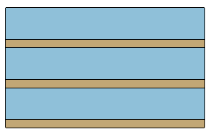 |
The total height of the window directly influences the shade depth required to protect the window from solar gain. Taller windows require deeper shades.
Glazing Is Shaded
Select this setting if you want light shelves to shade windows and other glazing for conceptual energy analysis. Proper shading greatly reduces cooling energy spent on a space with large areas of unprotected glazing.
In the conceptual model, automatic light shelves are external only, and they cannot be manipulated separately from their windows. However, you can manually create light shelves or other types of shades (such as awnings) for the conceptual model by using mass surfaces.
Shade Depth
When you select Glazing is Shaded, use the Shade Depth setting to specify the width of light shelves on the model.
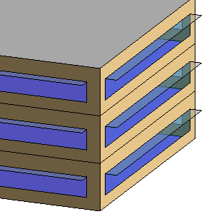
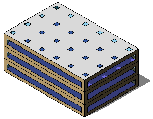
Target Percentage Skylights
Specify the percentage of roofs that should be skylights. This value is also known as the skylight-to-roof ratio (SRR). The default is 0%.
| Target Percentage Skylights = 5%. Skylight Width & Depth = 3’. | Target Percentage Skylights = 10%. Skylight Width & Depth = 4’. |
 |
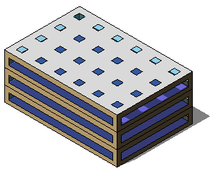 |
Skylight Width & Depth
When you specify a value for Target Percentage Skylights, use this setting to specify the size of the skylights.
Enter a dimension defining the width and depth of the skylights. For example, enter 4’ to specify skylights that are 4 feet wide by 4 feet deep.