Follow these guidelines when using Energy Analysis for Autodesk® Revit®, regardless of the analysis mode you choose in the Energy Settings dialog.
Also see the Best Practices topics listed below for additional guidelines that are specific to the chosen analysis mode.
Review the location
Energy analysis uses assumptions based on the geographic location of the model. In addition to affecting weather information, the location impacts the carbon content of the electricity supplied to the project.
Before starting an analysis, check the specified location in the Energy Settings dialog to make sure it is appropriate for the model. In the Location dialog, select the appropriate weather station using the Internet Mapping Service option.
If you change the model's location or other energy settings, when you run a new energy simulation, select Create New for the Green Building Studio Project in the Run Energy Simulation dialog. This setting ensures that the updated location and other settings are used in the analysis. See Specify the GBS Project for Energy Analysis.
Create masses or walls to define shading objects
If nearby buildings or structures will shade your building, you can model them to ensure that the energy analysis incorporates their effects on your building. For the energy analysis, you can hide or omit any buildings that do not directly shade the model.
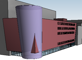
To create a shading object that represents a nearby structure, create a simple mass form that approximates the size and position of the other building. Do not apply mass floors to this mass. When a mass does not have mass floors, Revit considers it to be a shading object for the purpose of energy analysis.
For example, in the following model, the gray blocks are masses that will be interpreted as shading objects on the building elements. However, when you create mass floors in the purple cylinder mass and when the simulation includes conceptual masses, the cylinder is considered for the analysis.
As an alternative, you can represent a nearby structure with a freestanding wall. To ensure that the energy analysis does not treat the wall as an additional space, clear the Room Bounding parameter for these walls. Then in the Energy Settings dialog, set Mode to Use Building Elements or Use Conceptual Masses and Building Elements.
Use thermal zoning
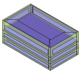
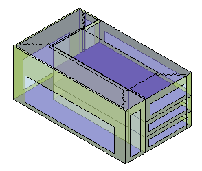
Thermal zoning can help to improve the accuracy of energy simulations. Automatic thermal zoning uses advanced algorithms to divide the geometry into thermal zones without additional modeling. You can also create custom thermal zones to reflect specific design parameters.
See About Automatic Thermal Zoning and About Custom Thermal Zoning.
|
|
|
Automatic thermal zoning |
Custom thermal zoning |
Review conceptual types for thermal properties
Before running an analysis, review the conceptual types specified using the Advanced Energy Settings dialog. Adjust them as appropriate for the model.
The default conceptual types do not necessarily match the climate conditions for the project location. For example, the default for Mass Exterior Wall is “Lightweight Construction – mild climate,” even if the project location is a cold climate like Moscow.
Review the energy model before submitting it for analysis
When you think the model is ready for energy analysis, click Create Energy Model
 . This tool generates the energy analytical model and allows you to examine it before the analysis begins.
Pan, zoom, and rotate a 3D view of the energy model to examine it closely. Look for unexpected geometry and areas that are not enclosed. Correct these issues before submitting the model for analysis.
Use meaningful names for analyses
When you start a simulation (an analysis), assign a concise, meaningful name so you can differentiate among simulations that use different forms and building parameters.