Enable surface-splitting, open the CAD model, and return the surface-splitting option to the default state.
Why Perform Surface-Splitting?
For the subsequent thermal analysis that we will preform on this model, a convection load is applied to the top of the circuit board. In the CAD model, the top of the board is a single surface. That means that the portions of the surface beneath the chip and edge connectors would receive the convection load even though they are not exposed to the ambient air. The solution to this problem is to perform surface-splitting when importing the CAD model.
The surface-splitting operation splits surfaces of CAD parts where they intersect other parts within the assembly. For this model, the single top surface of the circuit board becomes six separate surfaces when surface-splitting is performed. The resultant surfaces are as follows:
- The exposed area of the top of the board (one surface). This is the surface where convective heat loss can occur.
- The area under the chip (one surface)
- The area under each of the edge connectors (four surfaces)
By default, surface-splitting in Simulation Mechanical is disabled.
Two Procedures for Opening the CAD Model
Depending upon whether you constructed the Circuit Board CAD model in SimStudio Tools, choose one of the following two procedures:
- If you are continuing from the tutorial, Create Circuit Board CAD Model in Autodesk SimStudio Tools, use Procedure I. We assume that SimStudio Tools is already started and the circuit board CAD model is open.
- If you did not create the circuit board CAD model in SimStudio Tools, or if you chose not to install the SimStudio Tools application, use Procedure II below. We assume that the Simulation Mechanical application is already started and no model is open.
Procedure I: Push the CAD Model from SimStudio Tools into Simulation Mechanical
- In Simulation Mechanical, click
 Tools
Tools Options Application Options. You can also access this command by clicking the application button in the upper left corner of the screen and clicking the Options button within the application menu.
 - Select the CAD Import tab.
- Click Global CAD Import Options.
- Activate the Yes radio button next to Split surface on import.
- Click OK to accept the global CAD import settings.
- Click OK to exit the Options dialog box.
- Switch over to the SimStudio Tools application.
- Click
 ADD-INS Simulate in Mechanical to transfer the model for analysis.
 - Jump to Step 2 of Procedure II and continue from there to the end of the page.
Procedure II: Pull an IGES CAD Model into Simulation Mechanical
- In Simulation Mechanical, click
 Open on the Quick Access Toolbar (QAT). The Open dialog box appears.
 - If the Recent Files option is selected, click the Open icon ( ) in the upper-left corner of the dialog box to browse for other files.
- Navigate to your tutorial models folder.
- Select the IGES Solid Files (*.igs; *.ige; *.iges) option in the CAD Files section of the Files of type pull-down menu.
- Click the Options button in the lower-left corner of the Open dialog box.
- Activate the Yes radio button next to Split surface on import.
- Click OK.
- Select the file Circuit Board.igs
- Click Open.
- If the Recent Files option is selected, click the Open icon (
- In the Choose Analysis Type dialog box, select Thermal Steady-State Heat Transfer and click OK.
- Click Yes when prompted about using the default Simulation Mechanical color pallette instead of the CAD model colors.
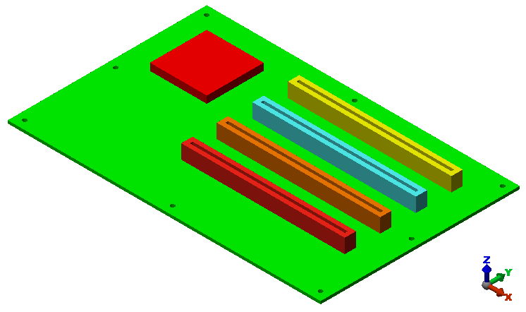
- Click Yes when prompted about importing CAD part names. The model opens in the FEA Editor environment as shown below.
- Click Tools Options Application Options.
- Select the CAD Import tab.
- Click Global CAD Import Options.
- Activate the No radio button next to Split surface on import.
- Click OK to accept the global CAD import settings.
- Click OK to exit the Options dialog box. Tip: You could choose to have the program prompt you concerning whether to perform surface-splitting whenever a CAD model is opened. However, if you do so, be aware that this additional prompt is not listed within the procedures in the Simulation Mechanical tutorials, which are based on default program settings.