Make a 3 x 3 pattern of the previously created hole. Suppress the middle hole in the pattern.
Procedure
- Click
 CREATE
 Pattern Rectangular Pattern.
 - Click and drag the mouse to draw a selection box enclosing only the previously created hole. Be careful not to enclose the short edge at the corner of the board. The Objects button in the RECTANGULAR PATTERN dialog box should indicate 1 selected. Important: Drag the selection box from left to right when enclosing the hole. If you drag from right to left, a crossing-box-selection is made (that is, everything the box intersects is selected, not just what it fully encloses). This action would result in making a pattern of repeated boards, not just repeated holes.Tip: If you accidentally select a wrong feature, click the red X next to the Objects button in the RECTANGULAR PATTERN dialog box to discard the selection. Then, repeat the selection process.
- Click the Directions button in the RECTANGULAR PATTERN dialog box.
- Click one of the long edges of the board. It does not matter which one you select; all long edges run in the X direction. Two direction arrows appear near the hole, as shown in the following image:
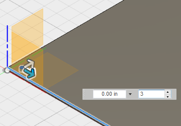
- Click one of the long edges of the board. It does not matter which one you select; all long edges run in the X direction. Two direction arrows appear near the hole, as shown in the following image:
- Click the direction arrow that is parallel to the long edge of the board and drag it towards the opposite end of the edge. The distance doesn't matter. We will specify the exact distance numerically.
Keep the cursor at the direction arrow. The input field for the total pattern distance in this direction is highlighted, allowing you to type the exact distance. If you move the cursor off of the direction arrow, the input field for the number of objects in this direction might become highlighted.
Note: You can switch the active input field between the distance and number of objects values by using the Tab or Shift-Tab key.- Type 10.4 in the distance input field, but do NOT press Enter at this time.
Keep the default number of objects in this direction (3), which is how many we want.
- Type 10.4 in the distance input field, but do NOT press Enter at this time.
- Click the direction arrow that is parallel to the short edge of the board and drag it towards the opposite end of the edge. Again, the distance doesn't matter.
Keep the cursor at the direction arrow. The input field for the total pattern distance in this direction should be highlighted.
- Type 6.4 in the distance input field, but do NOT press Enter at this time.
The board should look like the following image:
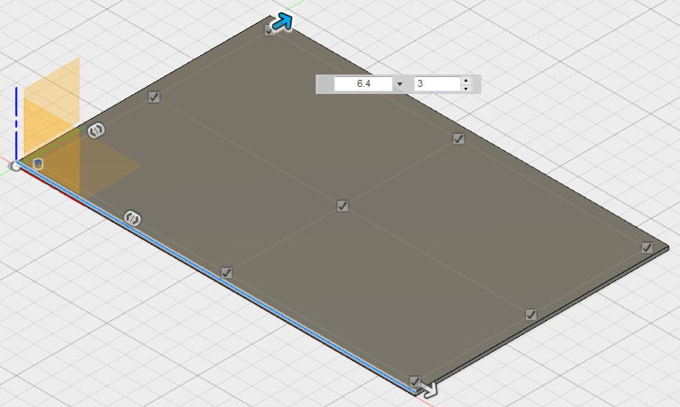
- Type 6.4 in the distance input field, but do NOT press Enter at this time.
- There is a checkmark next to each of the nine holes in the pattern. We need to exclude the hole at the very center of the board. Click the checkbox next to the center hole to deselect it, eliminating this hole from the rectangular pattern.
- Press Enter (or click OK) to complete the command and create the pattern of eight holes. The board should look like the following image:
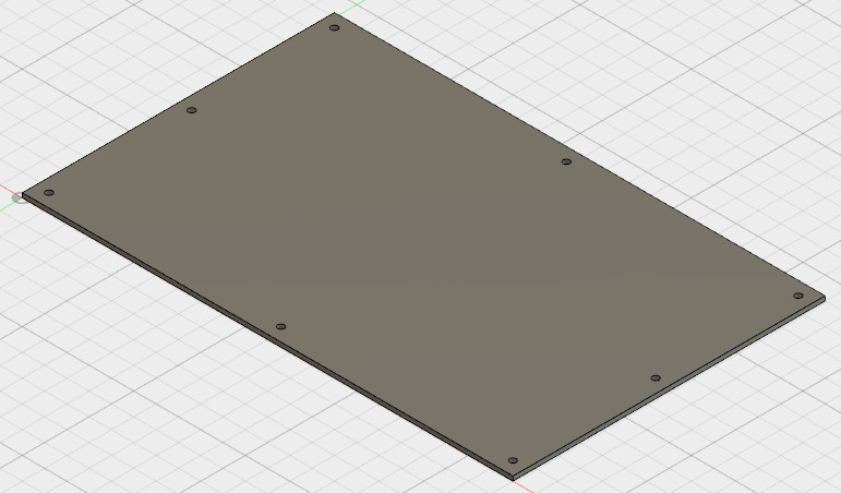
- Press Enter (or click OK) to complete the command and create the pattern of eight holes. The board should look like the following image:
- This completes creation of the board. In the Quick Access Toolbar (QAT), click
 Save. It is a good idea to save your work periodically as the CAD model progresses.
We add the chip and edge connectors in the upcoming pages.