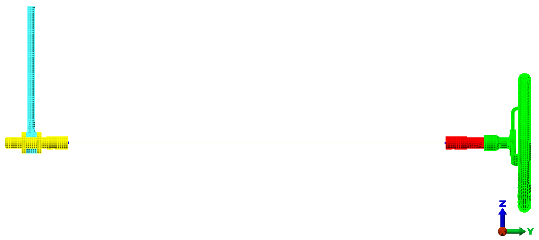
Next, use the Centroid Creator to locate the centroids at the ends of the crank and wheel stub shafts, to connect the end surfaces to the centroids, and to connect the two centroids with a beam element.
- Click
 View
View  Navigate Orientation Right View.
 - With
 Selection Shape Point or Rectange and
  Selection Select Surfaces active, click and drag the mouse to draw a selection window enclosing only the right edge of the crank subassembly, as shown below:
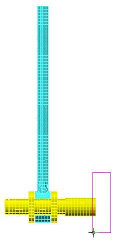
- Click
 Draw Design Centroid Creator. The Centroid Creator dialog box appears. Note that Part 3, surface 5 is already listed in the Primary Centroid Geometry box. Additionally, the Part number has been set automatically to 5, the first available unused part number.
 - Activate the option, Connect centroid to geometry with "spokes."
- Activate the option, Connect primary centroid to secondary centroid.
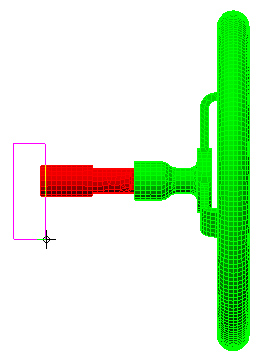
- Click and drag the mouse to draw a selection window enclosing only the left edge of the wheel subassembly, as shown below:
- Click the Add button to the right of the Secondary Centroid Geometry box.
- Click OK. The model appears as shown in the following image: