There is a set of spokes at each end of the geometry created by the Centroid Creator. The spokes and the spanning line element were initially created in a single part number. To idealize the connection, we want to use a beam element for the spanning member (the longest line) and rigid elements for the spokes.
Each set of lines comprising a rigid element group must be assigned a unique part number. A rigid element set consists of lines sharing a single common node (the master node). The nodes at the opposite end of each line are slave nodes, which move exactly as the master node does. For this reason, the spokes at one end of the span must be on a separate part number, and the spokes at the opposite end on another part number. In this procedure, we will reassign the part numbers and define the element type for all three line element parts.
- Right-click the Part 5 heading in the browser (tree view) and choose Isolate from the context menu. All of the parts, except those made by the Centroid Creator are hidden.
- With the
 Selection
 Select Lines option active, click and drag your mouse to draw a selection rectangle enclosing the spokes at the left end of the model.
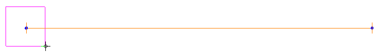
- Click
 Draw Modify Attributes. The Line Attributes dialog box appears.
 - Type 6 in the Part field.
- Click OK. A new part heading appears in the browser.
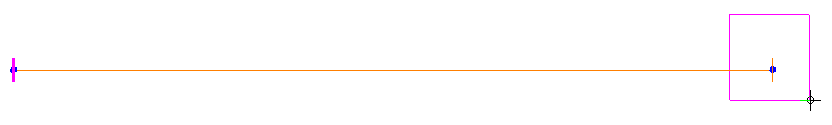
- Click and drag your mouse to draw a selection rectangle enclosing the spokes at the right end of the model.
- Click Draw Modify Attributes.
- Type 7 in the Part field.
- Click OK. Another part heading appears in the browser.
- Right-click the Element Type heading under Part 5 in the browser and choose Beam.
- Click the Element Type heading under Part 6 in the browser to select it.
- Holding down the Ctrl key, click the Element Type heading under Part 7 in the browser to select it also.
- Right-click on one of the two selected headings and choose Rigid from the context menu.