Compute the stress and strain in each ply of the laminate subjected to in-plane and bending loads.
The computed ply stresses and strains can be expressed in either the global coordinate system or the principal material coordinate system of each individual ply.
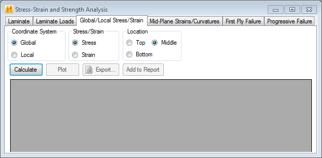
Once a laminate has been defined in the Laminate tab and loads have been applied in the Laminate Loads tab, switch to the Global/Local Stress/Strain tab and click the Calculate button to compute the ply stresses and strains (see image below).
Note: Three different options in this tab can be used to control the results computed and displayed. These are described below.
- Coordinate System - Change the coordinate system in which the ply stresses and strains are expressed. Selecting global displays the lamina stresses and strains in the global coordinate system. Selecting local displays the lamina stresses and strains in the local (or lamina) coordinate system (i.e., the principal material coordinate system of the lamina).
- Stress/Strain - Request stresses or strains to be computed for each ply of the laminate.
- Location - Specify the location (top, middle, or bottom) within each ply where stresses or strains will be computed. If top is selected, the stresses or strains are computed at the top of each ply. Similarly, if middle or bottom is selected, stresses or strains are computed at the middle or bottom of each ply respectively. Refer to the Creating a New Laminate section for interpretation of the top and bottom of a particular ply.

After ply stresses or strains have been computed and displayed, click Plot to plot the distribution of ply stresses or strains through the thickness of the laminate. The resulting plot window has a number of icons for various plotting options. For information on using these plotting options, please refer to ChartFX documentation available online.