Calculate individual ply thicknesses for a filament wound composite.
Navigate to to view the display shown below.

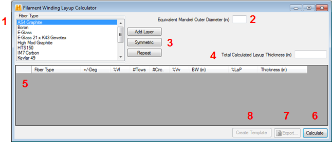
As shown above, eight fields are used to define the specifics of the filament winding process to be analyzed:
- Fiber Type - Displays the fiber type which will be used when adding a new layer (ply) to the layup. The fiber types listed in this window are the same fibers located in the data file tree within the Fibers branch. This also sets the fibers end area (total cross-sectional area a tow of fibers contributes to a layer thickness) used in the winding calculation.
- Equivalent Mandrel Outer Diameter - Specifies the diameter of the mandrel on which the winding will be performed. For non-circular cross-sections, the mandrel's diameter is determined by taking the perimeter length divided by π.
- Layer Build Options - The Add Layer, Symmetric, and Repeat buttons are used to build the filament winding layup (See Create a New Laminate for help). A filament-winding layer usually consists of a ±θ angle. Filament winding inherently deposits a +θ and a -θ onto the mandrel. This occurs when the fiber delivery head travels back and forth across the mandrel as it rotates.
- Total Calculated Layup Thickness - Total thickness of all the wound layers added together.
- Winding Ply Layers - The ply layers are added here. The columns of data are defined as follows:
- Fiber Type - Fiber type for the designed layer or ply.
- +/- Deg - The winding angle relative to the longitudinal axis of the mandrel. The calculator will assume a ±θ winding layer (e.g. input 20° and the calculator assumes a ±20° layer). Input angles can be between -90° and 90° only.
- Angles usually range from ±5° to around ±85° relative to the longitudinal axis of the mandrel. These angles are referred to as "helical" angles.
- When a fiber is wound around the mandrel's circumference while slowly advancing down the length of the mandrel, the winding is called a "hoop" layer. This layer is wound very close to 90° relative to the axis of the mandrel. A hoop layer is usually wound onto the mandrel in only one pass from one end of the mandrel to the other.
- Input angles of ±90° will result in unrealistic thicknesses. Therefore hoop angles for winding can be determined by:
cos-1 (Bandwidth/Circumference)
- %Vf - The fiber volume percentage for a given layer. This value must be input as a percentage, not as a decimal (i.e. 60 not 0.60).
- # Tows - Number of tows being wound onto the mandrel for each layer. A tow is defined as one yarn or roving of a fiber. For example, one tow of 12,000 filaments of graphite. Usually more than one tow of fiber is wound at a time. This collection of tows makes up a flattened winding ribbon called the winding band.
- # Circ - Total number of winding circuits in a layer. A winding circuit is one traverse of the winding head from one end of the mandrel and back again. A hoop winding around the mandrel will cover the mandrel in 0.5 winding circuits. Therefore, always input 0.5 circuits for hoop layers.
- %Vv - Void volume percentage. The layer thickness will be increased by this percentage if a value greater than zero is input here. This value must be between 0% - 30% and input as a percentage, not as a decimal (i.e. 10 not 0.10).
- BW (in.) - Total bandwidth of the winding band (includes all tows in a band). This usually needs to be measured on the mandrel as the band is being wound. The bandwidth entered here does not have any effect on the layer thickness. It is only used to calculate the percent of band overlap.
- %LaP - Percentage of band overlap "+%" or band gap "-%" relative to the overall circumference for a given layer.
- Thick (in) - Total ± layer thickness.
- Calculate - Once the input has been completed, complete the analysis by clicking the Calculate button. The output boxes will show the results of the defined analysis. The following calculated results are displayed:
- %LAP - Percentage of band overlap "+%" or band gap "-%" relative to the overall circumference for a given layer (e.g. 84% means that the bands overlap 84% of the bandwidth when resolved into the circumferential direction). The %LAP must fall between 100% and -100%.
- Thickness - Based upon the input, this is the total ± layer thickness.
- Total Calculated Layup Thickness - Total thickness of all the wound layers added together.
- Export - Click Export to print the tabulated Failure Envelope results to a *.csv file compatible with Microsoft Excel.
- Create Template - Save the calculated winding layup as a template in the Thickness/Angle Template branch of the data file tree.