There are two ways to create extruded features, from a sketch profile or from a primitive.
When you create extrusions from a sketch profile, the extruded result that you specify, such as a solid, or a surface, determines the geometry that you can select. For example, when you specify a surface extrusion, you can select open or closed loops made up of sketch curves, or projected face edges. When you specify a solid extrusion, with no preselected geometry, you can select either curves or regions. If you preselect a region, you cannot select individual curves or loops to extrude, and if you preselect a curve or loop, you cannot select a region.
Creating sketch features from primitive shapes automates the sketching and extrusion process. In the Primitive panel, you can use Box to create a square or rectangular feature or body, for example, or Cylinder to create a cylindrical feature or body. You select a start plane for the sketch, define the profile, and then create an extruded solid.
Create an extrusion from a profile
- In the browser, select an unconsumed 2D sketch that represents a profile or cross-section of the extruded feature or body you want to create.
- On the ribbon, click
3D Model tab
 Create panel
  Extrude
 .
.
If there is only one profile in the sketch, it is selected automatically. Otherwise, select a sketch profile.
- In the Extrude dialog box, click Profile and then select the profile to extrude.
Note: For part features, you can use a shared sketch as a profile. In the browser, click the plus sign beside the feature that contains the sketch you want to use. Then right-click the sketch icon, and click Share Sketch. A sketch that you use in more than one feature is automatically shared.
- If you select an open profile in a part file, specify whether you want to Match Shape and, if so, select the side to keep.
If selected, Match Shape creates a flood-fill type operation. The open ends of the profile extend to a coedge, or face. The required faces quilt together to form a complete intersection with the extruded body.
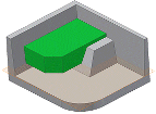
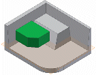
When deselected, the open profile closes by extending the open ends of the profile to the part. It closes the gap between them by including edges defined by the intersection of the sketch plane and the part. Creates the extrusion as if you specified a closed profile.
- If there are multiple bodies in the part file, click the Solids selector in the Shape tab of the Extrude dialog box to choose the participating body.
- In the Shape tab of the Extrude dialog box, specify the Output type:
- Solid
 . Creates a solid feature from an open or closed profile. Open profile selection is not available for base features.
Note: Use a window to select multiple closed profiles when using the Extrude command.
 - Surface
 . Creates a surface feature from an open or closed profile. Functions as a construction surface on which to terminate other features, or a split tool to create a split part, or split a part into multiple bodies. Surface selection is not available for assembly extrusions or primitives.
- Solid
- In the Shape tab of the Extrude dialog box, specify an Operation:
- Join
 . Adds the volume created by the extruded feature to another feature or body. Not available for assembly extrusions.
- Cut
 . Removes the volume created by the extruded feature from another feature or body.
- Intersect
 . Creates a feature from the shared volume of the extruded feature and another feature. Deletes material that is not included in the shared volume. Not available for assembly extrusions.
- New Solid
 . Creates a solid body. If the extrusion is the first solid feature in a part file, this selection is the default. Select to create a body in a part file with existing solid bodies. Each body is an independent collection of features, separate from other bodies. A body can share features with other bodies.
- Join
- Using the Extents list and related options, determine the method for ending the extrusion and set its depth:
- Distance. (Default) Extrudes in one direction only. Establishes the depth of extrusion between start and end planes. For a base feature, shows negative or positive distance of extruded profile or entered value. The extrusion end face is parallel to the sketch plane. Click a different direction to flip the direction of the extrusion.

- Distance – Distance. Extrudes in two directions, one positive and one negative. To activate Distance-Distance, choose Extents > Distance and then click Asymmetric. Enter depth values for each distance. Click Flip to reverse the two direction vectors so that the positive depth becomes negative, and the negative depth becomes positive.
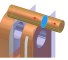
- To Next. (Not available for base features or assembly extrusions.) Selects the next possible face or plane on which to terminate the extrusion in the specified direction. Dragging the profile flips the extrusion to either side of sketch plane. Use the Terminator selector to select a solid or surface on which to terminate the extrusion and select a direction for the extrusion.
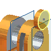
- To. For part extrusions, selects an ending point, vertex, face, or plane on which to terminate the extrusion. For points and vertices, terminates the part feature on a plane parallel to the sketch plane which passes through the selected point or vertex. For faces or planes, terminates the part feature on the selected face, or on a face that extends beyond the termination plane.
For assembly extrusions, you can select sketch points, vertices, faces, and planes that reside on other components. To be selected, work planes and work points must reside on the same assembly level as the assembly extrusion you are creating.
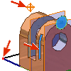
- Between. (Not available for base features.) For part extrusions, selects beginning and ending faces or planes on which to terminate the extrusion. For assembly extrusions, selects a face or plane on which to terminate the extrusion. You can select faces and planes that reside on other components. The faces or planes that you select must reside on the same assembly level as the assembly extrusion that you are creating.
For assembly extrusions, selects a face or plane on which to terminate the extrusion. You can select faces and planes that reside on other components. The faces or planes that you select must reside on the same assembly level as the assembly extrusion that you are creating.
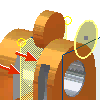
- All. Extrudes the profile through all features and sketches in the specified direction. Dragging the edge of the profile flips the extrusion to either side of the sketch plane. The Join operation is not available.
- Symmetric. Extrudes in two directions with half the total value. Enter the distance of the extrusion.
- Asymmetric. Extrudes in two directions with different values. Enter a value for the positive distance and enter a second value for the negative distance.
- Distance. (Default) Extrudes in one direction only. Establishes the depth of extrusion between start and end planes. For a base feature, shows negative or positive distance of extruded profile or entered value. The extrusion end face is parallel to the sketch plane. Click a different direction to flip the direction of the extrusion.
- On the More tab of the Extrude dialog box, clarify ambiguous termination options by choosing any of the following:
- Alternate Solution. For To and Between extents, when a solution is ambiguous, such as termination on a cylinder or an irregular surface, specifies alternate termination plane. Not available for Distance, Distance-Distance, To Next, and All extents.
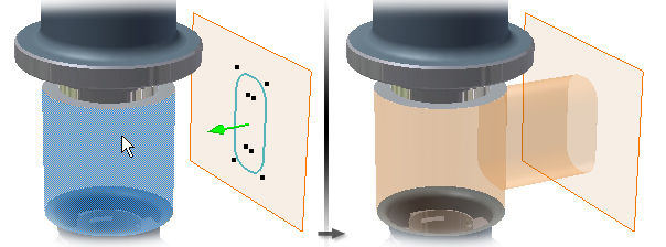
- Minimum Solution. When options for termination faces are ambiguous, specifies that the extrusion terminates on the closest face. With Minimum Solution selected, the extrusion terminates on the near side of the cylinder:
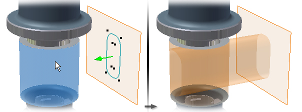
With Minimum Solution deselected, the extrusion terminates on the far side of the cylinder:
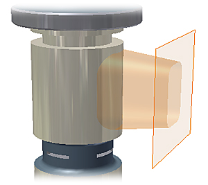
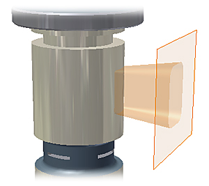
- Taper Angle. For all Extents types, sets a taper angle of up to 180 degrees normal to the sketch plane. The taper extends equally in both directions. In the graphics window, an arrow shows the taper direction. When you use Distance-Distance, you can apply a taper angle to both directions.
A positive taper angle increases section area along the extrusion vector:
 A negative taper angle decreases section area along the extrusion vector:
- Infer iMate . (Optional) Places an iMate on a closed loop such as an extruded cylinder, revolved feature, or hole. Autodesk Inventor attempts to place the iMate on the closed loop most likely to be useful. In most cases, place only one or two iMates per part.
- Click OK.
 Show Me How to Create an Extrusion Using the Mini Toolbar
Create an extrusion from a primitive
- Click
3D Model tab
 Primitives panel
  Box
Box
 or
3D Model tab
  Primitives panel
  Cylinder
 .
.
- Select a sketch plane. The sketch plane can be an origin plane, a work plane, or a planar face.
- Define the shape by doing one of the following:
- For a box, click to define the center and then click to define a corner.
- For a cylinder, click to define the center and then click to define the diameter.
- If there are multiple bodies in the part file, click the Solids selector in the Shape tab of the Extrude dialog box to choose the participating body.
- In the Shape tab of the Extrude dialog box, specify an Operation:
- Join
 . Adds the volume created by the extruded feature to another feature or body. Not available for assembly extrusions.
- Cut
 . Removes the volume created by the extruded feature from another feature or body.
- Intersect
 . Creates a feature from the shared volume of the extruded feature and another feature. Deletes material that is not included in the shared volume. Not available for assembly extrusions.
- New Solid
 . Creates a solid body. If the extrusion is the first solid feature in a part file, this selection is the default. Select to create a body in a part file with existing solid bodies. Each body is an independent collection of features, separate from other bodies. A body can share features with other bodies.
- Join
- Using the Extents list and related options, determine the method for ending the extrusion and set its depth:
- Distance. (Default) Extrudes in one direction only. Establishes the depth of extrusion between start and end planes. For a base feature, shows negative or positive distance of extruded profile or entered value. The extrusion end face is parallel to the sketch plane. Click a different direction to flip the direction of the extrusion.

- Distance – Distance. Extrudes in two directions, one positive and one negative. To activate Distance-Distance, choose Extents > Distance and then click Asymmetric. Enter depth values for each distance. Click Flip to reverse the two direction vectors so that the positive depth becomes negative, and the negative depth becomes positive.

- To Next. (Not available for base features or assembly extrusions.) Selects the next possible face or plane on which to terminate the extrusion in the specified direction. Dragging the profile flips the extrusion to either side of sketch plane. Use the Terminator selector to select a solid or surface on which to terminate the extrusion and select a direction for the extrusion.

- To. For part extrusions, selects an ending point, vertex, face, or plane on which to terminate the extrusion. For points and vertices, terminates the part feature on a plane parallel to the sketch plane which passes through the selected point or vertex. For faces or planes, terminates the part feature on the selected face, or on a face that extends beyond the termination plane.
For assembly extrusions, you can select sketch points, vertices, faces, and planes that reside on other components. To be selected, work planes and work points must reside on the same assembly level as the assembly extrusion you are creating.

- Between. (Not available for base features.) For part extrusions, selects beginning and ending faces or planes on which to terminate the extrusion. For assembly extrusions, selects a face or plane on which to terminate the extrusion. You can select faces and planes that reside on other components. The faces or planes that you select must reside on the same assembly level as the assembly extrusion that you are creating.
For assembly extrusions, selects a face or plane on which to terminate the extrusion. You can select faces and planes that reside on other components. The faces or planes that you select must reside on the same assembly level as the assembly extrusion that you are creating.

- All. Extrudes the profile through all features and sketches in the specified direction. Dragging the edge of the profile flips the extrusion to either side of the sketch plane. The Join operation is not available.
- Symmetric. Extrudes in two directions with half the total value. Enter the distance of the extrusion.
- Asymmetric. Extrudes in two directions with different values. Enter a value for the positive distance and enter a second value for the negative distance.
- Distance. (Default) Extrudes in one direction only. Establishes the depth of extrusion between start and end planes. For a base feature, shows negative or positive distance of extruded profile or entered value. The extrusion end face is parallel to the sketch plane. Click a different direction to flip the direction of the extrusion.
- On the More tab of the Extrude dialog box, clarify ambiguous termination options by choosing any of the following:
- Alternate Solution. For To and Between extents, when a solution is ambiguous, such as termination on a cylinder or an irregular surface, specifies alternate termination plane. Not available for Distance, Distance-Distance, To Next, and All extents.
- Minimum Solution. When options for termination faces are ambiguous, specifies that the extrusion terminates on the closest face. With Minimum Solution selected, the extrusion terminates on the near side of the cylinder:

With Minimum Solution deselected, the extrusion terminates on the far side of the cylinder:

- Taper Angle. For all Extents types, sets a taper angle of up to 180 degrees normal to the sketch plane. The taper extends equally in both directions. In the graphics window, an arrow shows the taper direction. When you use Distance-Distance, you can apply a taper angle to both directions.
A positive taper angle increases section area along the extrusion vector:
 A negative taper angle decreases section area along the extrusion vector:
- Infer iMate . (Optional) Places an iMate on a closed loop such as an extruded cylinder, revolved feature, or hole. Autodesk Inventor attempts to place the iMate on the closed loop most likely to be useful. In most cases, place only one or two iMates per part.
- Click OK.