Sketched features include extruded profiles and shapes, revolved shapes, sweeps, lofts, coils, and ribs.
Extrude
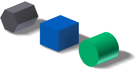
An extruded feature adds depth to an open or closed profile, or a region. Extrusions are building blocks for creating and modifying solid bodies within a part. You specify the direction, depth, taper angle, and termination method for the extrusion. Extruded features can create new bodies in a multi-body part file. A new solid body creates an independent body which you can edit as a separate entity. A solid body can share features with other solid bodies.
Extrusions can modify bodies with a join, cut, or intersect operation; you can use extruded assembly features to cut through other parts.
When defining the termination extents of extruded features, it is good practice to use Distance, Distance-Distance, and To Next options. If the model changes and your specific termination face no longer exists, re-create the extrusion. If you specify a specific distance, or the next possible face, the extrusion remains intact.
When creating extrusions in part files from open profiles, you can propagate shapes. Shape propagation describes solutions that are defined through the extension of the open ends of the profile and by the shape of the body. Shape propagation generates a feature that is robust to topology changes in the part body caused by editing features higher up in the feature tree. The extruded feature is not dependent on a profile defined by specific referenced edges and sketch lines.
- To add a feature to a part in an assembly, extrude from and to a plane or face of another part.
- To cut through one or more assembly components, create a profile in an assembly sketch, and then extrude as an assembly feature. Its origin and termination planes can be on a part face or a work plane. Selected faces and planes must reside at the same level in the assembly as the extrusion that you are creating.
Note: You cannot use open profiles to create extrusions as assembly features.
Revolve
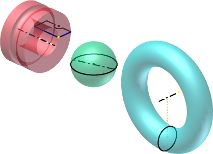
The Revolve command creates a feature or new solid body by rotating one or more sketched profiles around an axis. Revolving around an axis on the sketch produces solid features such as disks, hubs, and beveled gear blanks. Revolving around an axis that is offset from the sketch creates solids with holes, such as washers, flasks, and conduits.
You can also use the Revolve command to create features having radial symmetry, such as cylindrical containers or O-rings. Such features can define the overall shape of a part (a base feature) or become details such as fins, webs, or struts.
If you create an assembly feature, only the solid output and cut operations are supported. Revolved assembly features can cut through other parts.
You can create a surface from a revolved profile, and then use it as a termination plane for other features, or a split tool for a split part.
You can use an open or closed profile to create a surface, which can be used as a construction surface or to design complex shapes.
Sweep

Sweep features or bodies are created by moving or sweeping one or more sketch profiles along a path. The multiple profiles you use must exist in the same sketch. The path can be an open or closed loop, but must pierce the profile plane.
A sweep feature usually requires a minimum of two unconsumed sketches—a profile and a path—on intersecting planes. In some cases, you can use a single unconsumed sketch for the profile and an existing model edge for the path. To control orientation of the swept profile, you can hold the profile constant to the path, or parallel to the original profile. To control scale and/or twist of a swept profile, select a guide surface or guide rail.

Traditional path sweeps are used for objects that have uniform profiles swept along a trajectory, such as gasket grooves and cabling or piping through an assembly.
Guide rail sweeps are used for objects that have nonuniform profiles that scale or twist along a trajectory, such as a complex handle for a consumer part.
Guide surface sweeps are used for objects that have uniform profiles swept along a nonplanar trajectory. The twist of the profile must maintain a given orientation to a selected surface, such as a machining operation on a cylindrical part.
Loft
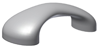
Loft features blend multiple profiles, called sections, and transition them into smooth shapes between profiles or part faces. The sections can be curves in 2D sketches or 3D sketches, model edges, or face loops. You can use rails, or a centerline and point mapping, to control the shape and prevent twisting. For open lofts, one or both end sections can be a sharp or tangent point. Loft can produce both solids and surface bodies.
Loft can be used to create complex, organic shapes for the automotive, marine, and consumer products industries. Use Loft to:
- Create a solid feature or new body.
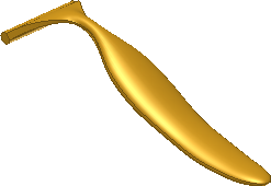
- Generate the shape, create a surface model, and then stitch the resulting surface quilt into a solid.
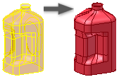
- Create lofted surfaces and use with the Sculpt command to create a shape, or modify the model.

Coil
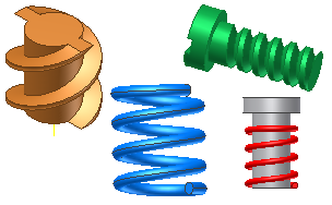
A coil creates a helix-based feature or body, such as a spring or threads on a cylindrical surface. A coil can be a new body in a multi-body part.
To create threads, you specify a coil profile that represents the shape of the thread, and use the cylinder center point to create the rotation axis.
You can use the Coil feature to create springs, but to design real spring models, use Spring Generators, which are available in assemblies in the Spring panel of the Design tab.
Rib
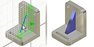
Use Rib to create ribs (thin-walled closed support shapes) and webs (thin-walled open support shapes) using an open or closed profile.
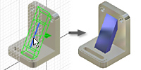
Ribs can have a thickness normal to the sketch plane and extend material planar to the sketch. Ribs can also have a thickness planar to the sketch and extend material normal to the sketch plane.
- Ribs can have a thickness normal to the sketch plane and extend material planar to the sketch.
- Ribs can have a thickness planar to the sketch and extend material normal to the sketch plane.
- Rib networks provide a series of intersecting thin-walled supports.
Define the cross section of a rib or web using an open or closed profile. You can project the profile to the next face, define its direction (to specify a rib or web shape), and thickness. You can add a draft or boss features to webs.
To create a rib network, specify multiple intersecting or nonintersecting profiles in a sketch. The same thickness, and draft if specified, is applied to the entire network.