How To ... Access the Z-Depth channel
| How To > Access the Z-Depth channel |
The 3ds Max default scanline renderer generates a multitude of additional data channels providing information about colors, texture coordinates, normals, transparency, velocity, coverage etc. All of these channels can be accessed for reading via MAXScript.
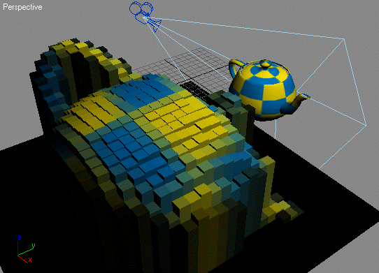
The following simple script will render an image including Z-buffer depth info and convert it into what is known as a "voxel landscape" using the depth data to generate geometry representing the single image pixels.
Deleting objects using wildcard pathname
Rendering the current view with Z-buffer data
Accessing the Z-buffer channel as greyscale mask

Step-By-Step:
First we make sure any voxel objects from past sessions have been deleted. We delete all objects starting with "VoxelBox" no matter what other characters the name contains.
Now we render the active viewport at 32x32 resolution and store the result in the variable rbmp . We request an additional Z-depth channel to be generated. The Virtual Frame Buffer will be disabled during rendering.
After rendering the image, we request a copy of the ZDepth channel as a greyscale mask. It will be stored in the bitma z_d .
We start a new progress indicator with a respective caption - it will be displayed in the status bar at the bottom of the UI.
Now we start looping through all lines in the rendered bitmap. The variable y will change from 1 to the height of the bitmap.
The progressupdate method requires a percentage value. We divide the current bitmap line number y by the total number of lines rbmp.height . This yields a result between 0.0 and 1.0
Multiplied by 100.0 it returns a percentage between 0.0 and 100.0.
Now we read a whole line of pixels from both the RGBA bitmap and its z-buffer. Note that bitmap indices are 0-based and count from 0 to height minus one. This explains the "minus one" in the vertical position value.
By counting from 1 to the width of the bitmap, we access each pixel of the current scanline.
Now we create a box with width and length equal to 10, and height equal to half the Z-buffer's grayscale value. We also set the X and Y position to every 10 th world unit based on the pixel's coordinates. Note that we have to use the negative y value to get the upper left corner appear up left. A bitmap starts up left, while the positive quadrant of the MAX world space starts down left. This way we mirror the vertical coordinate to get a valid representation of the bitmap in the viewport.
Using the RGB color of the rendered pixel, we assign a new wireframe color to the new box.
Viewport_related_node_properties
We also set its box's name to a unique name with the base "VoxelBox"
Using the Script
To run the script, simply press Ctrl+E or select Tools > Evaluate All in the MAXScript Editor's menu. Make sure the current viewport shows the desired view to be rendered. The progress bar will let you know that the script is working. The result will be a group of boxes representing both color and depth of the rendered bitmap with the upper left corner at the world origin.
Where to go from here
Using this script as starting point, you could play with the creation of different object types like Spheres, Cylinders etc. A more advanced version could alter the Z position of vertices in a mesh grid based on the camera Z depth for a real heightmap elevation.
