This command is applicable to Autodesk Nastran In-CAD for Inventor only. It is not available within SOLIDWORKS. Use the Offset Surfaces command to manually designate one or more surfaces of a solid part to be converted to a surface representation (to be meshed with shell elements). You can specify an offset distance from the original surface location to where you want the offset surfaces placed. The thickness parameter for the shell elements is assumed to be twice the offset distance, but you can override the default thickness value. The action of this command is similar to the Midsurfaces tool in that the original solid part is suppressed and replaced with a surface representation. The Offset Surfaces tool differs in two ways—you can specify the offset, and you can select only a portion of the solid (specifically, one or more faces) as the basis of the shell element representation.
To use the Offset Surfaces tool:
- Click
Autodesk Nastran
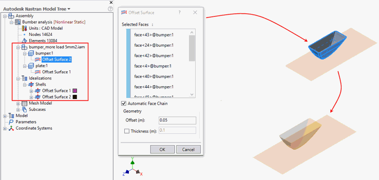
 Prepare Offset Surfaces. The Offset Surface dialog appears:
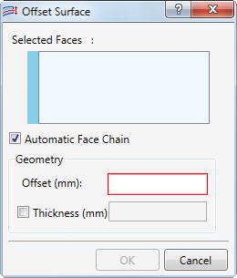
- If you want to select a continuous chain of tangent faces with a single click, leave the Automatic Face Chain option activated. If you only want to select the individual faces you directly click, deactivate the Automatic Face Chain option.
- In the model canvas, click the faces that you want to offset and use as the basis of the shell element representation. Each clicked face is listed in the Selected Faces box (along with all tangent if the Automatic Face Chain option is activated). You cannot select faces of two parts in the same Offset Surfaces instance. Therefore, you need to undividually execute the Offset Surfaces command for each part that you want to convert to a surface representation.
- Optionally, to revise the selection set, select and right-click one or more items in the Selected Faces list. From the context menu, you can:
- Delete the selected items, or
- Clear All items from the list.
- Enter the desired Offset distance. A positive offset moves the surface into the solid body to which the face belongs. A negative offset moves the surface away from the solid body.
- Optionally, activate the
Thickness option and enter a user-specified thickness value. The default value is twice the offset distance.
 Since the default Thickness = 2 * Offset, the default thickness will be negative if you specify a negative offset value. In such cases, be sure to override the
Thickness and enter an appropriate positive value.
Since the default Thickness = 2 * Offset, the default thickness will be negative if you specify a negative offset value. In such cases, be sure to override the
Thickness and enter an appropriate positive value.
- Click
OK to complete or
Cancel to abort the operation. The solid body associated with the selected faces is suppressed and replaced by an offset surface representation. The new Offset Surface is listed in the
Idealizations\Shells branch of the model tree.
A pop-up message may appear indicating that some features have been lost due to geometry modification.
- Click Details to see which features have been lost.
- Click Close to dismiss the message.
In the following example, the "plate" part had been converted previously to a surface representation, and the "bumper" part is now being converted too. The Automatic Face Chain option is active, allowing all outer surfaces of the solid to be selected in a single click: