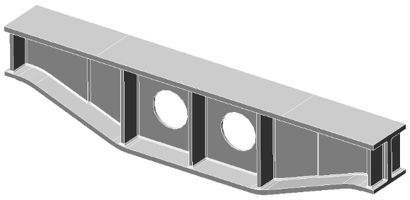
In this tutorial, we mesh the tapered support beam shown in the following image:
Note: In a subsequent tutorial, we analyze the support beam model and discover that the displacement and stress results exceed design target values. We then use Autodesk SimStudio Tools to modify the CAD geometry to increase the strength and stiffness of the beam. Finally, we repeat the analysis and verify that displacement and stress results are acceptable. This subsequent tutorial demonstrates how you can modify CAD geometry from any source using SimStudio Tools (for example, to bring analysis results into a desired target range).
SimStudio Tools is installed automatically when you install Autodesk Simulation Mechanical.
Features Illustrated:
- Opening a step (*.stp) CAD model
- Solid meshing