This topic details contact settings for linear, thermal, and electrostatic analyses. For nonlinear analyses, please refer to the Surface Contact Settings page within the Nonlinear Analyses branch.
Smart bonding Tab
This tab appears only for bonded or welded contact in linear, heat transfer, or electrostatic analyses in which smart bonding has been enabled. Please see the Smart Bonding page for details on the associated settings.
Friction Tab
This tab appears only for the following contact types.:
- Surface
- Sliding/no separation
- Separation/no sliding
- Edge contact
The Friction tab contains the following settings:
Coefficient of Friction: Activate this checkbox and specify a suitable value in the adjacent input field (typically, 0 < Coef. of Friction ≤ 1).
Surface contact direction: Choose the method used to determine the direction in which the contact elements acts (that is, the direction of the contact reaction force). (The direction of the friction force is at a right-angle to the surface contact direction.) The available methods are:
- Calculate by matching directions: This is the defaults option. The program calculates the direction from the normals of the elements at each node. This is the recommended method. If the mesh is coarse and the surface curved, some of the elements may be non-flat (i.e. the fourth node is not coplanar with the other three). In this case the default method may not result in valid directions. To achieve valid directions, you can increase the value in the Direction tolerance angle field.
- Normal to the first part/surface: When the first part or surface in the contact pair has flat elements and the second part or surface does not, use this option to make the contact direction normal to the first part or surface.
- Normal to the second part/surface: When the second part or surface in the contact pair has flat elements and the first part or surface does not, use this option to make the contact direction normal to the second part or surface.
Direction tolerance angle: (Default = 20 degrees.) You can increase this tolerance to successfully calculate the surface contact direction when the surface elements are distorted (that is, not flat).
In Figure 1, a block is on a fixed surface. A normal force, N, is applied to allow the generation of a friction force, Ff. A static coefficient of friction of μ exists between the block and the fixed surface. A lateral force, F is applied to the block. A spring is placed between the block and a wall to create a statically stable model. Ff can range from 0 to μN as follows:
|
For F <= μN: Ff=F Fs=0 |
|
For F >= μN: Ff=0 Fs=F |
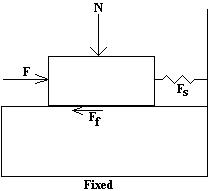
Figure 1: Static Friction
Once the lateral force exceeds the maximum value of the friction force, the friction force goes to zero and no longer resists the motion. If what happens after this is important, a Mechanical Event Simulation (MES) analysis using surface to surface contact should be performed. In MES, a dynamic coefficient of friction can be defined to calculate the friction force after the static friction force is exceeded.
Shrink fit Tab
This tab is applicable to Static Stress with Linear Material Models analyses only. The following options are available:
Interference:- Automatic: Determine the amount of interference (that is, the intensity of the fit) from the CAD geometry. If your model is CAD-based and there is geometric interference in the CAD assembly, the interference is removed from the geometry and the meshes are matched to each other in a net fit (zero-interference, zero-clearance). However, the interference from the original CAD assembly is retained numerically. You have to define shrink fit contact in Simulation Mechanical (assuming you want to quantify the effects of the interference). The
Automatic
interference option is activated by default, and the interference magnitude is assigned automatically on a node-by-node basis (that is, it can be non-uniform).
Important: In order for Automatic interference assignment to work correctly, you must define contact by explicit surface pairs. Automatic interference will not work for part-to-part contact or for the Default (global) contact type.
- Manual: Activate this option to manually specify the amount of interference. If you are using a hand-built model or a CAD model without geometric interference, you can specify a uniform
radial
interference between the contacting parts. Specify the radial interference in the input field that is adjacent to the Manual radio button. For example, if a bearing with a bore of 40 mm diameter is pressed onto a 40.03 mm diameter shaft, the radial interference is 0.015 mm (half of the diametral interference):
(40.03-40) / 2 = 0.015
Manually specifying the interference is a quick way to determine the effects of various intensities of fit without having to modify the CAD geometry. It also makes it easy to determine the effects of interferences when they are not represented in the CAD model or for hand-built models.
You can model a CAD assembly with a net fit between the contacting parts. A hand-built assembly must be modeled with matched surfaces (net fit). In either case, you can specify a uniform interference within the Shrink fit tab of the Contact Options dialog. In addition, you can override the geometric interference, if any, in a CAD model with a user-specified, uniform interference value.
- Calculate by matching directions: This is the defaults option. The program calculates the direction from the normals of the elements at each node. This is the recommended method. If the mesh is coarse and the surface curved, some of the elements may be non-flat (i.e. the fourth node is not coplanar with the other three). In this case the default method may not result in valid directions. To achieve valid directions, you can increase the value in the Direction tolerance angle field.
- Normal to the first part/surface: When the first part or surface in the contact pair has flat elements and the second part or surface does not, use this option to make the contact direction normal to the first part or surface.
- Normal to the second part/surface: When the second part or surface in the contact pair has flat elements and the first part or surface does not, use this option to make the contact direction normal to the second part or surface.
Direction tolerance angle: (Default = 20 degrees.) You can increase this tolerance to successfully calculate the surface contact direction when the surface elements are distorted (that is, not flat).
Thermal Tab
This tab is applicable to surface contact in steady-state and transient heat transfer analyses. The following options are available:
Thermal resistance: Choose the method you are using to define the thermal resistance:
- Total Resistance: Define the total thermal resistance of the contact pair. The total resistance that you define in the Value: field is evenly distributed over the contact surface area. (For 2D planar models, the total resistance is for the thickness of the mating parts. For 2D axisymmetric models, the total resistance is for 1 radian.)
- Distributed Resistance: Define the resistance on a per-unit-area basis. The resistance you define in the Value: field is divided by the area of the contact pair and applied to the model.
- Calculate by matching directions: This is the defaults option. The program calculates the direction from the normals of the elements at each node. This is the recommended method. If the mesh is coarse and the surface curved, some of the elements may be non-flat (i.e. the fourth node is not coplanar with the other three). In this case the default method may not result in valid directions. To achieve valid directions, you can increase the value in the Direction tolerance angle field.
- Normal to the first part/surface: When the first part or surface in the contact pair has flat elements and the second part or surface does not, use this option to make the contact direction normal to the first part or surface.
- Normal to the second part/surface: When the second part or surface in the contact pair has flat elements and the first part or surface does not, use this option to make the contact direction normal to the second part or surface.
Direction tolerance angle: (Default = 20 degrees.) You can increase this tolerance to successfully calculate the surface contact direction when the surface elements are distorted (that is, not flat).