You use the fields and options in the section of the Stress Linearization utility shown below to define the Stress Classification Line (SCL) for your model. In addition, you use these settings to specify the local coordinate system on which the graphed stress tensors are based.
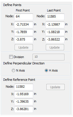
Figure 1: Stress Linearization Utility – Define Points and Perpendicular Direction Controls
What is a Stress Classification Line (SCL)?
- A stress classification line is a straight line that generally extends from free surface to free surface of a material. In other words, a stress classification line is typically drawn across the thickness of a given section of a solid. However, non-solid elements are also supported (plate, shell, 2D), and you can define the SCL in any direction (as long as it intersects elements in your model). The endpoints of the SCL do not have to coincide with FEA nodes.
- Stress tensor results along the SCL are presented in a graph. The tensors are based on a local coordinate system dictated by the SCL endpoints, a third (reference) point, and the N Axis or H Axis option you choose.
Point and Axis Definition Controls
- First Point:
- In this field, enter the start point of your SCL. (See How to Specify Points below.)
- Last Point:
- In this field, enter the endpoint of your SCL. (See How to Specify Points below.)
- Define Perpendicular Direction:
- The stress values along the SCL are reported as six stress tensors based on a local coordinate system. Therefore you need to define the three perpendicular directions on which the tensor calculations are based. These axes are named the T, N, and H. The positive T axis is defined by the direction of the SCL, First Point to Last Point (or Last Point to First Point if you use the
Invert T Axis
option). The third point you specify (see
Define Reference Point
below) defines either the
N Axis or the
H Axis direction, depending on which radio button you choose to activate.
- If the N Axis option is selected, a line perpendicular to the T axis passing through the Reference Point defines the N axis direction. The H axis is then defined as the axis perpendicular to both the T and N axes.
- If the H Axis option is selected, a line perpendicular to the T axis passing through the Reference Point defines the H axis direction. The N axis is then defined as the axis perpendicular to both the T and H axes.
- Regardless of the option you select, the N axis is the cross product of the T and H axes (following the right-hand rule).
- You can use the Invert T Axis option to reverse the direction of the positive T axis. (See the Toolbar Definitions page.)
- Define Reference Point:
- Specify the reference point used to indicate the direction of the N or H axis. (See Define Perpendicular Direction above and How to Specify Points below.)
The figure below shows the local axis configuration if the Define the N Axis option is selected, and the T axis direction is not inverted:
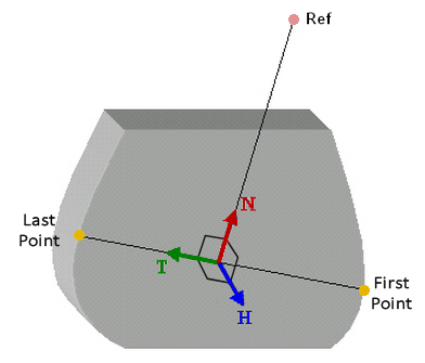
Figure 2: SCL and Local Axis Orientation (using the N Axis Option under Define Perpendicular Direction)
How to Specify Points
You can specify the First Point, Last Point, and Reference Point in three ways:
- Type the node number into the Node field.
- Select a point graphically in the model canvas and click one of the three available Update buttons (under First Point, Last Point, or Define Reference Point ).
- Type the coordinates of any point on the model into the X, Y, and Z fields. The SCL must intersect elements in your model, but SCL endpoints and reference points do not have to be at FEA nodes.