In this lesson you initialize Civil View, if necessary, and then import the geometry you will use to build a model of a roadway with traffic.
Initialize Civil View:
- On the 3ds Max menu bar, choose Civil View
 Initialize Civil View.
 If the Civil View menu says "Start Civil View" or shows a list of Civil View commands, then Civil View is already initialized on your system, and you can skip ahead to "Import the Civil 3D data." If you need to change the resource kit or the start mode, you can use the Civil View Preferences dialog. If you need to change the units, use Customize
Units Setup. After you choose Initialize, 3ds Max displays the Initialize Autodesk Civil View dialog,

- On the dialog, choose these settings:
- System Units: Meters
- Country Resource Kit: US METRIC
- Start Mode: Automatic
- Click OK.
A dialog warns that you need to restart 3ds Max for these changes to take effect.
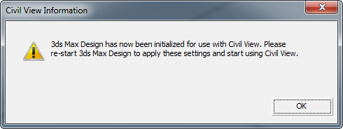
- Close 3ds Max and then restart it.
Now you are ready to work with Civil View.
If you have already used Civil View, you can skip this procedure.
Import the Civil 3D data:
- From the Civil View menu, choose Geometry Import Civil 3D (VSP3D) File.
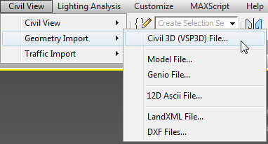
3ds Max opens the Civil 3D Import Panel.
- On the Civil 3D Import Panel, click Open.
This button is at the upper left.
3ds Max opens a file dialog.
- In the /tutorials/import/Civil_3D_files folder, locate the file linkroad-stage2.vsp3d. Highlight it, and then click Open.
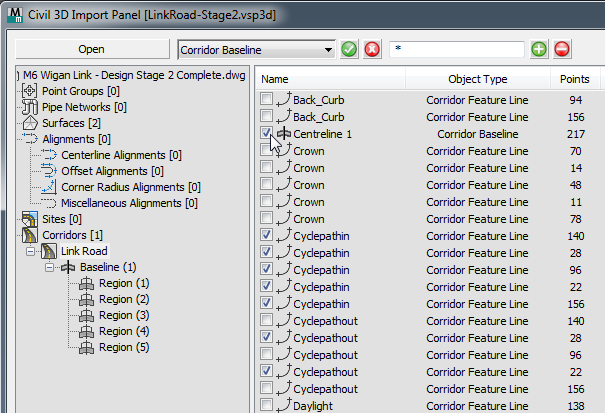
- Now the Import Panel shows geometry from the Civil 3D file.
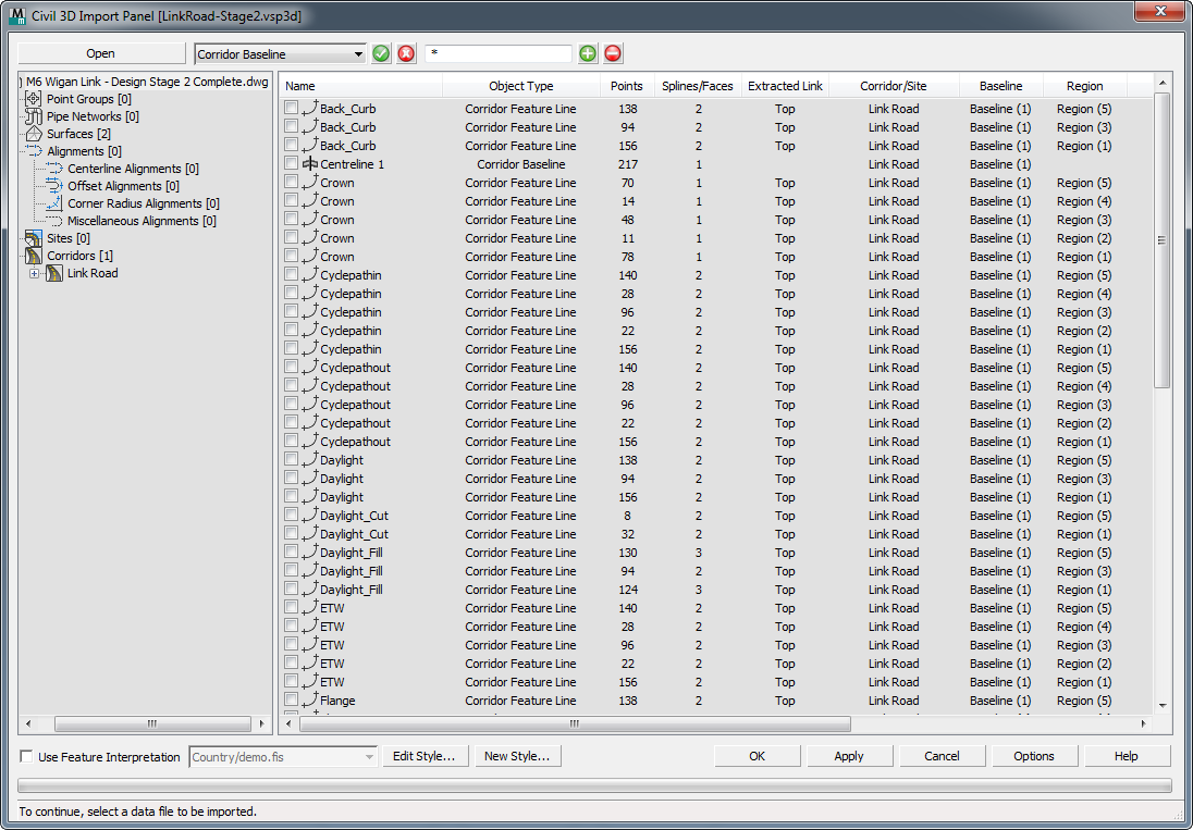
The window at the left shows the hierarchy of the original scene, and the window at the right shows individual line and surface objects.
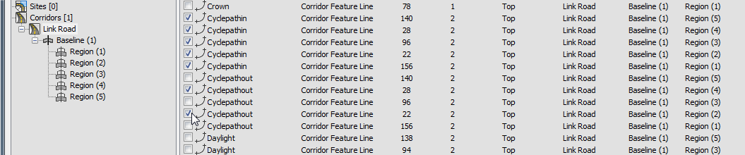
Note: VSP3D is not a native Civil 3D format, but you can export a VSP3D file from Autodesk Civil 3D; for example, to use its data in a Civil View model. - In the left-hand hierarchy, click to highlight the Link Road entry. Then in the right-hand list, click the checkboxes to select the following features:
- The surfaces labeled Region (1) through Region (5).
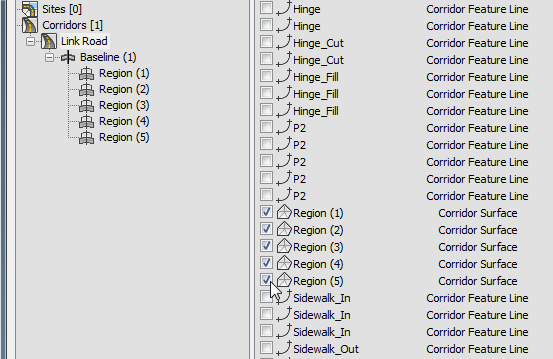
- All feature lines labeled Cyclepathin.
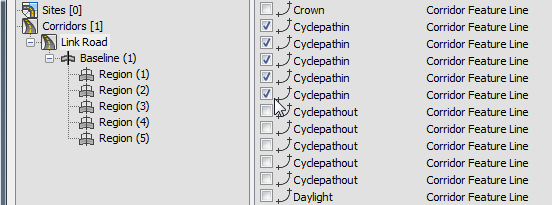
- The feature lines labeled Cyclepathout, but only those from Region (2) and Region (4).
- The corridor baseline labled Centreline 1.
- The surfaces labeled Region (1) through Region (5).
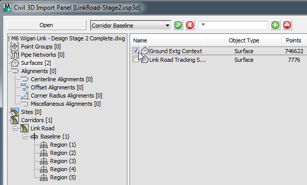
- In the left-hand hierarchy, click to highlight the Surfaces entry, then in the right-hand list, click to select the surface Ground Extg Context.
 Tip: When you import civil-design geometry into 3ds Max, it is best to import only those elements you know you need to use. Additional geometry just slows down 3ds Max without contributing to the visualization model. If you need to import additional elements, you can do so at a later time.
 - Click OK.
3ds Max prompts you to adjust the origin of the scene.

When civil-design data is based on surveyor's data, the coordinates can be very large and offset from an origin point of (0,0). Loading the data without shifting the origin can lead to strange viewport behavior and more importantly, to inaccurate modeling because of roundoff error. To avoid these problems, always use Global Import Shift.
- Click Yes.
3ds Max prompts you to use Feature Interpretation Styles.
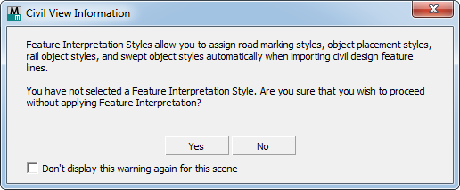
- Click Yes to skip this dialog. You will add feature interpretations later.
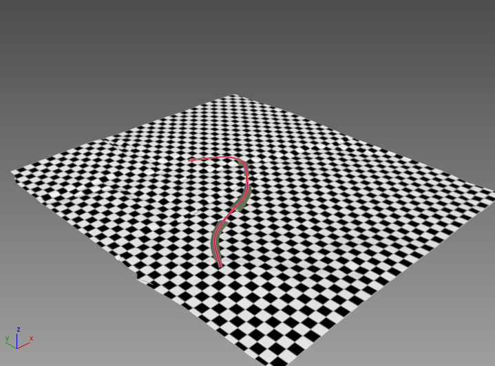
3ds Max displays a progress bar while it imports the geometry. After a pause, you can see the result in the viewport: There is a ground plane, and the lines and surfaces that define the roadway.
 Tip: You might want to
 zoom in to get a better view of the imported geometry. Also, if the scale does not appear to be correct, choose Customize Units Setup, then make sure that Metric is chosen and Meters is the active unit.
 By default, the ground plane has a checkered texture. You will change this in the next lesson.
Save your work:
- Save the scene as my_roadway_imported.max.