Use the Raised Feature option on the Feature Machining panel to create a raised (male) feature from a selected vector, usually vector text, which you can then machine using the Feature Machining toolpath. This toolpath is commonly used in conjunction with the Machine Relief toolpath.
Using the Feature Machining panel, you can:
- control whether any central cavity in the vector is removed or not during the feature machining process; and
- control what edge of the vector the tool meets when cutting it from the block of material.
To create a raised feature:
- Select the vector from which you want to create a raised feature.
- In the
3D Toolpaths area, click the
Create Feature Machining Toolpath
 button to display the
Feature Machining panel.
button to display the
Feature Machining panel.
- Select Raised Feature.
- In the Feature Height box, enter the height of the raised feature that you want to create.
- Select how the tool machines the selected vector:
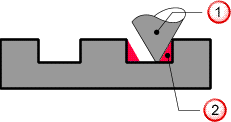
- Vector at Top Edge — This option places the selected
Feature Tool in contact with the top edge of the selected vector during the machining process.
 Feature tool.
 This material is not cut by the feature tool.
If this option is selected, you can choose how you want sharp corners to be machined.
Sharpen At Top — If selected, sharp internal corners are sharpened at the top of the feature, provided an angled tool is used.
Sharpen At Bottom — If selected, sharp external corners are extended and sharpened at the bottom of the feature, provided an angled tool is used.
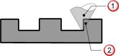
- Vector at Bottom Edge — This option places the selected
Feature Tool in contact with the bottom edge of the selected vector during the machining process.
 Feature tool
This material is cut by the feature tool.
Feature tool
This material is cut by the feature tool.
- Vector at Top Edge — This option places the selected
Feature Tool in contact with the top edge of the selected vector during the machining process.
- In the
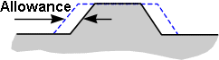
Feature Allowance box, enter a value if you want to keep or remove extra material around the selected vector. This sets the distance between the boundary of the selected vector and the selected feature tool. Enter a positive value to keep material or a negative value to remove it.
- If the selected vector contains a central cavity that you want to remove with your selected feature tool, click to select the
Clear inner islands option. If you select this option, any Feature Allowance you have already created and
Overcut Distance that you specify is ignored by the feature tool you use to machine the raised feature.
If Clear inner islands is deselected, the feature tool can only remove material inside of a central cavity as far as the Feature Allowance and Overcut Distance allow.
- Set the limitations for machining:
- If you want to leave an allowance around the boundary of the selected vector, including any central cavity that it may contain, select Use constant allowance around vector.
- If you want to machine around the boundary of the selected vector, select the Outer vector defines machining limit option. If the selected vector contains a central cavity, the cavity is not removed using this option. The Feature Allowance box is also unavailable.
- Select the machining strategy that you want to use:
- Profile Only — This strategy enables the cutting tool to make profile passes around the feature you have selected.
- Area Clear — This strategy enables the cutting tool to clear an area of material based on the boundary of the feature you have selected, then make profile passes around the feature.
Note: The selected feature is not machined using the Area Clear strategy. A protected area is created around the selected feature during the machining process.
If you have selected Area Clear, enter a value in the Overcut Distance box to remove any ridge of unwanted material that might appear around the feature.
For example, if a Ball Nose cutting tool is used as the feature toolwith an Area Clear strategy, a ridge of unmachined material may appear around it:
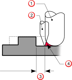 Ball nose tool.
Engraving tool.
Ball nose tool.
Engraving tool.
 Feature allowance
 An overcut is necessary to remove this material.
Note: The Overcut Distance should normally be equal to the radius of the Feature Tool used in an Area Clear strategy.
An overcut is necessary to remove this material.
Note: The Overcut Distance should normally be equal to the radius of the Feature Tool used in an Area Clear strategy.
- Enter a value in the Allowance box to specify an offset from the machined vector.
- To perform the machining strategy that you have selected as a series of passes in the Z direction, select
Do Multiple Z Passes.
- Enter the number of Z passes you want to make in the Num Slices box.
- Click Linear Spacing. This distributes the Z passes through the feature material.
- Click Add to add a new slice.
- Highlight a value in the box on the left of the Do Multiple Passes area and click Delete to delete an individual value.
- Select how the cutting tool reaches the depth you have defined.
- Drop Tool — If selected, ArtCAM checks for collisions between the tool geometry and the machined relief. This reduces the possibility of gouging.
- Project Tool — If selected, ArtCAM ignores the tool geometry and the centreline of the tool is projected onto the relief.
- Select the
Cut Direction you want to use.
- Climb — Select the option to rotate the cutter in the same direction as the feed motion. The option is selected by default.
- Conventional — Select the option to rotate the cutter in the opposite direction to the feed motion.
Note: Set the default cutting direction on the Options panel. - Enter a value in the Tolerance box to specify how closely you want the cutting toolto follow the shape of the selected feature.
- If you want to change the height at which the tool makes rapid moves between toolpath segments and define the Home position for the tool, click the
Machine Z control bar to expand its settings.
- Safe Z — Enter the height at which your selected tool makes rapid moves between toolpath segments. This value must be sufficient to clear any clamps used to hold your material block or sheet in position.
- Home X, Y and Z — Enter the X, Y and Z coordinates of the tool's start and end position. This should be a safe distance away from your material block or sheet.
- Click Select next to Feature Tool to display the Tool Database dialog, from which you can select the tool you want to use.
- Click Setup next to Material to define the size of your material block.
- In the Toolpath area, enter a Name for the toolpath. If you leave this box blank, the toolpath is named after the type of toolpath you are creating. For example, if you create three Feature Machining toolpaths and do not rename them, they are named Feature Machining, Feature Machining 1 and Feature Machining 2.
- Ensure the vectors along which you want to create the
Feature Machining toolpath are selected, then:
- Click Calculate Later if you want to calculate the toolpath at a later time either by itself or as part of a batch. The toolpath is added to the Project Tree under the Toolpaths item, but is red to indicate it has not been calculated.
- Click
Calculate Now to calculate the toolpath now. A progress bar is displayed in the
Status Bar area during calculation, then the toolpath is added to the Project Tree under the
Toolpaths item. It is black to indicate it has been calculated.
A wireframe representation of calculated toolpath is displayed in the 3D view.
Note: You can edit a toolpath's settings either before or after it has been calculated.
After you have calculated the toolpath, you can simulate it.