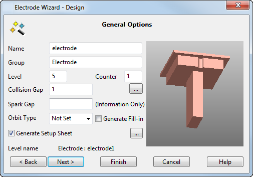
Use this page to enter the general options for the electrode. An image of the electrode is displayed in the graphic window alongside the options:
- Use the option on the dialog as follows:
- Name — Enter the name of the electrode. It is also the name of the level on which the electrode is created.
- Group — This is name of the group that contains the level of the electrode.
You can enter a name only if the level given in Level is currently unnamed.
- Level — This is the number of the level on which the electrode is created. If the level is currently unnamed, it is named using the string in Name.
- Counter — Sets the counter number used in electrode names. Each electrode is named using the text in the Name and Counter values.
- Collision Gap — (Not available for electrodes created outside the wizard) The
Electrode Wizard - Design avoids collisions between the electrode base and the active solid. The electrode base is automatically trimmed back to avoid collisions. The gap between the electrode base and the active solid is set using the
Collision Gap value:
In the example below, the electrode base is trimmed to avoid collisions.
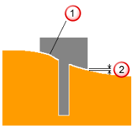
 Electrode trimmed back
 Collision gap
 — Click this button to open the
Additional Electrode Details dialog.
— Click this button to open the
Additional Electrode Details dialog.
- Spark Gap — This value appears on the set up sheet. It is the distance required between the electrode and the product to generate a spark, and depends upon the electrode size and material, and the desired finish quality. EDM companies provide recommended spark gap values, also known as the Undersize value — seeElectrode Family. This value is not used by PowerShape, but is exported to PowerMill. If it is undefined, leave the text box empty.
- Orbit Type — You can set an orbit pattern to control the movement of the machine head during EDM. The movement takes up the difference in dimensions between the electrode, which is machined
Undersize, and the actual cavity required in the workspace. Select from:
Hemisphere (3D)
Circle (2D)
Square (2D)
Star (2D)
Custom
None (No orbit needed)
Not set (unknown)
- Generate Fill-in Surface — Select this option to createfill-in surfaces that cover the burn regions of the electrode. The fill-in surfaces are created on the Electrode Fill-in Surfaces level. This level is in the same group as the electrode. If the level doesn't exist, a new one is created.
- Generate Setup Sheet — If selected, setup sheets for the electrode are created. By default, two setup sheets are created:
Machining (Electrode Detail sheet) — This sheet is created for each electrode. By default, it contains an isometric view of the electrode, which shows the electrode's dimensions. It also contains the rotation and the origin of the electrode in the bottom left corner.
EDM (GA sheet) — This sheet contains a top view of the model and electrodes in the model. Balloons mark the origin and rotation of each electrode. This sheet is updated each time you create an electrode, and generates the setup sheet to show all the electrodes for this model.
- — Click this button to open the
Electrode Setup Sheet Control dialog.
- Next — Click this button to move to the Electrode Family page of the Electrode Wizard - Design.