This page enables you to select the region you want to make the electrode for.
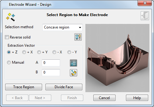
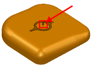
The initial direction of electrode extraction is shown on your model as an arrow, pointing in the direction of the +Z axis.
If the wrong workplane is selected, you can select another one using the
Workplane list
 in the bottom left corner of the
PowerShape status bar. While this page of the wizard is displayed, you can change the general tolerance in the
Status bar.
in the bottom left corner of the
PowerShape status bar. While this page of the wizard is displayed, you can change the general tolerance in the
Status bar.
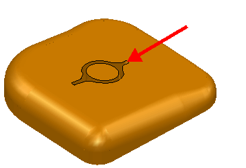
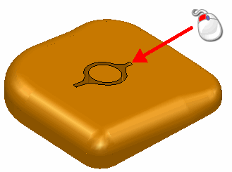
As you move the cursor over the solid, regions highlight. These are the regions where you can create an electrode. You can create missing geometry automatically in the case where geometry is missing for one or more of the electrodes required to burn a region.
To select the region to make your electrode:
- Choose the
Selection method to determine the type of region that is highlighted:
- Single Face — Highlights only single faces.
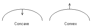
- Concave Region — Highlights concave regions on the active solid.

- Convex Region — Highlights convex regions on the active solid.

The surface normal of the solid is important in determining whether a region is concave or convex. Convention is for the surface normal to point away from the solid material. You can see this in the following two open solids.
- Select the Reverse Solid option to reverse the active solid if required.
- Click the
Options
 button to open the
Electrode page of the
Options dialog and change the settings as required.
button to open the
Electrode page of the
Options dialog and change the settings as required.
- Define the extraction vector.
The electrode is created in the +Z direction by default. In addition to the traditional +Z direction, electrodes can also be created in X and Y direction or along any vector you define. You can define a vector using the following options:
 Position — Click this button to display the
Position dialog and use position-entry tools to specify the extraction vector. As you progress through the wizard, the electrode, base, and holder are created along this vector.
Position — Click this button to display the
Position dialog and use position-entry tools to specify the extraction vector. As you progress through the wizard, the electrode, base, and holder are created along this vector.
 Surface normal — Select this option to define the burn vector by clicking on a surface, where the surface normal is in the required direction.
Note: See Side-sparking and vector-burn electrodes. - Select a region on the solid where you want to create an electrode. If you click a highlighted region, it is selected and changes colour and is shown in the graphical window of the wizard. Any regions already selected are removed from the selection.
 Tip: Press and hold the Shift key and click to add and remove regions.
Press and hold the Ctrl key and click to toggle in or out of the region.
Use box selection to select regions. Only whole faces within the box are selected, making it easier to select groups of faces. You can also use box selection with the Shift and Ctrl keys to add and remove regions. To include an emboss feature, select its surrounding faces when selecting the burn region.
You can further specify your region selection using the following options:
-
 — These buttons are displayed on the dialog when you select a region. Use these buttons to display a different view of the region in the display window.
- Trace Region - You can trace a closed curve on the active solid to define the region. Click the
Trace Region button to display the
Create Composite Curve toolbar. Use the toolbar to define a curve. The curve is coloured the same as regions selected using the automatic method. You can create electrodes from composite curves that have been defined externally and preselected before starting the wizard.
Tip: Trace Region is intended to be used when the automatic selection fails because the solid is linked badly or the region is too complex. Using Trace Region takes longer to compute the burn region, so try the selection method first whenever possible.
- Divide face — You may want to select only a portion of a solid face. Click this button to display the Divide Face in Solid dialog, which enables you to divide a face of a solid into two pieces. You can also divide multiple faces.
-
- If you select these objects and restart the wizard, they represent the selected regions and are used to create the electrode. You can add other regions to these.
- You can also use these objects to create a solid representing the electrode. You can then register a solid as an electrode and add the electrode to the EDM setup sheet.
- Click Next to display the Extension Distance Options page.
Surfaces and composite curves are created from the selected regions and shown as selected. You can use these objects in the following ways: