This topic describes how to open an Autodesk Civil 3D 2019 drawing and view the Autodesk Civil 3D objects in a prior version of the software. It also describes interoperability between Autodesk Civil 3D 2019.2, Autodesk Civil 3D 2019.1, Autodesk Civil 3D 2019, and AutoCAD Civil 3D 2018.
Opening an Autodesk Civil 3D 2019 Drawing in a Prior Version of AutoCAD Civil 3D
- Drawings saved in
Autodesk Civil 3D 2019 can be opened in AutoCAD Civil 3D 2018.
Note: Fixed vertical curves created with the Fixed Vertical Curve (Parabolic, High/Low Point, Parameter, Length) and Fixed Vertical Curve (Circular, High/Low Point, Parameter, Length) commands are not backward compatible with AutoCAD Civil 3D 2018. See the Profiles section below for more information.
- To open an Autodesk Civil 3D 2019 drawing and view the Autodesk Civil 3D objects in a version of the software prior to AutoCAD Civil 3D 2018, set the PROXYGRAPHICS system variable value to 1 in Autodesk Civil 3D 2019 to save the graphics with the drawing and then use the Save As command to save the drawing to a prior drawing file format. When you open the drawing in a prior version of the software, the Autodesk Civil 3D objects will be displayed as proxy graphics.
Interoperability Between Autodesk Civil 3D 2019.2 and Autodesk Civil 3D 2019, Autodesk Civil 3D 2019.1, or AutoCAD Civil 3D 2018
Crossing Objects in Profile View
- Crossing objects in profile view and their labels will be displayed as proxy graphics in Autodesk Civil 3D 2019, Autodesk Civil 3D 2019.1, or AutoCAD Civil 3D 2018. If you make changes to the source objects in a prior version of the application and then save and reopen the drawing in Autodesk Civil 3D 2019.2, the crossing objects and their labels will be updated in Autodesk Civil 3D 2019.2.
Opening an Autodesk Civil 3D 2019.2 drawing in Autodesk Civil 3D 2019, Autodesk Civil 3D 2019.1, or AutoCAD Civil 3D 2018
Rail Platform Edges
- Rail platform edge feature lines can be viewed in Autodesk Civil 3D 2019, Autodesk Civil 3D 2019.1, or AutoCAD Civil 3D 2018.
- If you make changes to the non-geometric properties of the rail platform edge feature line or the dynamically-linked alignment in a prior version of the application (such as editing the properties or the style), the dynamic links between the feature line and the alignment are preserved when you save the drawing and re-open it in Autodesk Civil 3D 2019.2.
- If you make changes to the geometry of the rail platform edge feature line in a prior version of the application, and then save the drawing and reopen it in
Autodesk Civil 3D 2019.2, the dynamic links between the feature line and the alignment will be removed and a message will be displayed on the feature line that it is out of date.
To update the feature line, run the Edit Platform Edge command, select the feature line, and click OK in the Edit Platform Edge dialog box.
- If you make changes to the geometry of the dynamically-linked alignment in a prior version of the application, the platform edge feature line will not be updated. If you save the drawing and reopen it in
Autodesk Civil 3D 2019.2, the dynamic links between the feature line and the alignment will be removed and a message will be displayed on the feature line that it is out of date.
To update the feature line, run the Edit Platform Edge command, select the feature line, and click OK in the Edit Platform Edge dialog box.
Opening an Autodesk Civil 3D 2019.2 drawing in Autodesk Civil 3D 2019, Autodesk Civil 3D 2019.1, or AutoCAD Civil 3D 2018
Interoperability Between Autodesk Civil 3D 2019.1 and Autodesk Civil 3D 2019 or AutoCAD Civil 3D 2018
Alignments
- Offset rail alignments that have cant information defined for them can be viewed and edited in Autodesk Civil 3D 2019 or AutoCAD Civil 3D 2018. However, the cant information is not available and cant views are not displayed in the drawing. Superelevation cannot be applied to an offset rail alignment in Autodesk Civil 3D 2019 or AutoCAD Civil 3D 2018 if cant was applied to it in Autodesk Civil 3D 2019.1.
- If you edit the parent rail alignment or the offset rail alignment in Autodesk Civil 3D 2019 or AutoCAD Civil 3D 2018 and then re-open the drawing in Autodesk Civil 3D 2019.1, the parent alignment and the offset alignment will be marked as being out of date.
- You may need to update the cant values and recreate the cant views in Autodesk Civil 3D 2019.1 if either the parent alignment or offset alignment has been edited in Autodesk Civil 3D 2019 or AutoCAD Civil 3D 2018.
Opening an Autodesk Civil 3D 2019.1 drawing in Autodesk Civil 3D 2019 or AutoCAD Civil 3D 2018
Profiles
- Vertical tangents created with the Float Tangent (Grade, Length) command are automatically converted to floating tangents which use a through point as their constraint type when you open an Autodesk Civil 3D 2019.1 drawing in Autodesk Civil 3D 2019 or AutoCAD Civil 3D 2018. When the drawing is re-opened in Autodesk Civil 3D 2019.1, the vertical tangents are restored to their previous constraint type of grade and length.
- Fixed vertical curves created with the Fixed Vertical Curve (Parabolic, High/Low Point, Parameter, Length) command in
Autodesk Civil 3D 2019.1 are automatically converted to use two points and a parameter as their constraint type when you open the drawing in AutoCAD Civil 3D 2018.
- If you do not edit the curves in AutoCAD Civil 3D 2018, they are restored to use the constraint type of Parabolic, High/Low Point, Parameter, Length when the drawing is re-opened in Autodesk Civil 3D 2019 or Autodesk Civil 3D 2019.1.
- If you edit the curves and save the drawing in AutoCAD Civil 3D 2018, the changes are preserved when the drawing is re-opened in Autodesk Civil 3D 2019.1 and the curves will use two points and a parameter as their constraint type.
- If you edit the curves and save the drawing in AutoCAD Civil 3D 2018, the changes are not preserved if the drawing is re-opened in Autodesk Civil 3D 2019. The version of the curve that was saved in Autodesk Civil 3D 2019.1 is restored when the drawing is re-opened in Autodesk Civil 3D 2019.1.
Opening an Autodesk Civil 3D 2019.1 drawing in Autodesk Civil 3D 2019 or AutoCAD Civil 3D 2018
Pipe Networks
- Pipe networks that use the Default Connection Point or Closest Connection Point options for connecting the pipes to structures can be viewed in Autodesk Civil 3D 2019 or AutoCAD Civil 3D 2018. However, if you edit the pipe network in Autodesk Civil 3D 2019 or AutoCAD Civil 3D 2018, the pipes will adjust and will be reset to the structure insertion points.
Opening an Autodesk Civil 3D 2019.1 drawing in Autodesk Civil 3D 2019 or AutoCAD Civil 3D 2018
Sample Line Data Shortcut References
- Sample line data shortcut references and section views created from them are displayed in the drawing when you open an
Autodesk Civil 3D 2019.1 drawing in
Autodesk Civil 3D 2019 or AutoCAD Civil 3D 2018.
- If you remove a sample line from the sample line group using Autodesk Civil 3D 2019 or AutoCAD Civil 3D 2018, the edit will be preserved when you reopen the drawing in Autodesk Civil 3D 2019.1.
- Other edits made in Autodesk Civil 3D 2019 or AutoCAD Civil 3D 2018, such as adding sample lines to the sample line group or editing a sample line, will not be preserved when you reopen the drawing in Autodesk Civil 3D 2019.1.
Opening an Autodesk Civil 3D 2019.1 drawing in Autodesk Civil 3D 2019 or AutoCAD Civil 3D 2018
Interoperability Between Autodesk Civil 3D 2019 and AutoCAD Civil 3D 2018
Profiles
- Fixed vertical curves created with the Fixed Vertical Curve (Parabolic, High/Low Point, Parameter, Length) and Fixed Vertical Curve (Circular, High/Low Point, Parameter, Length) commands are not backward compatible with AutoCAD Civil 3D 2018.
- You can use the Convert Curves command to convert the fixed parabolic curves so they are compatible with AutoCAD Civil 3D 2018, but the fixed circular curves cannot be converted and will be missing when the drawing is opened in AutoCAD Civil 3D 2018.
- If you do not convert the parabolic curves, those curves will also be missing when the drawing is opened in AutoCAD Civil 3D 2018.
Note: Fixed vertical curves created with the Fixed Vertical Curve (Parabolic, High/Low Point, Parameter, Length) command in Autodesk Civil 3D 2019.1 are automatically converted to use two points and a parameter as their constraint type if you open the drawing in AutoCAD Civil 3D 2018. For more information, see the section above.
- After the curves are converted, they cannot be converted back to their original constraint type.
For more information, see To Change the Constraint Type of Vertical Curves for Backward Compatibility.
Opening an Autodesk Civil 3D 2019 drawing in AutoCAD Civil 3D 2018
Subassemblies
- A validation process occurs in the Subassembly Composer for
Autodesk Civil 3D 2019 to check whether the geometry in rail subassemblies that depends on items which have ApplyAOR specified will be updated correctly. Open previously-created rail subassembly PKT files that use cant in the Autodesk Subassembly Composer and update them if needed.
For more information, see About Cant Validation in the Subassembly Composer and About Defining Cant for a Subassembly.
Cant validation in rail subassembly PKT files
Page Setup in Drawings Created from Drawing Template (DWT) Files
- When they are opened in
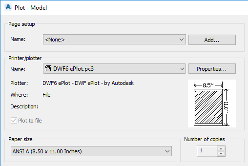
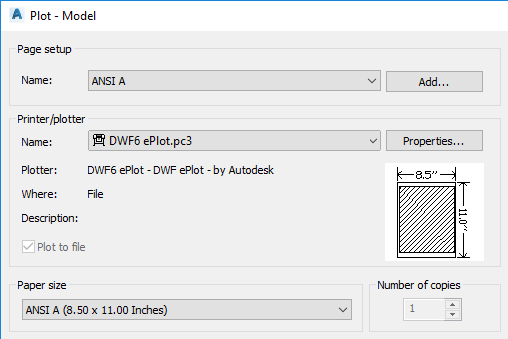
Autodesk Civil 3D 2019, drawings that were created using DWT files from AutoCAD Civil 3D 2017 and AutoCAD Civil 3D 2018 may default to showing the <None> page setup in the Plot dialog box and do not retain the name of a new selection (they return to the <None> selection) if you select a different page setup from the list.

To resolve this issue, the page setup definitions that you want to use need to be resaved in Autodesk Civil 3D 2019.
- Click
Output tab
 Plot panel
  Page Setup Manager to display the
Page Setup Manager dialog box.
- Select the page setup you want to use.
- Click Modify to display the Page Setup dialog box, and then click OK.
- Repeat this process for each page setup you want to use.
After resaving a page setup, when you open the Plot dialog box and select the page setup, the selection is retained.

- Click
Output tab
Selecting a page setup in Autodesk Civil 3D 2019