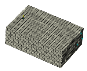
The mold mesh is prepared in a single step, or in two steps, depending upon the mold model.
Regardless of the mesh type selected for the part, transient cool mold meshes are composed of tetrahedral (3D) elements. The 3D mold mesh is created in a single step, by default, for CAD/STL molds. If you want to check the integrity of the mold surface mesh before the 3D mesh is generated, you can stop the meshing process after surface mesh generation and 3D mesh in a second step.

- CAD mold models
- For imported CAD mold models, the mold can be meshed in a single step.
- STL mold models
- For imported STL molds, the mold can be meshed in a single step, but to reduce the element count it is advisable to stop the meshing after the surface mesh has been generated to apply longer edge lengths to the mold external surfaces. The 3D mesh can then be generated.
- Mold Block Wizard molds
-
Access the wizard by clicking
 (). The wizard creates a mold around your CAD part, inserts, cooling channel curves and runner system curves. You can either create a CAD mold block, or you can create the mold as regions. By default, the mold is generated as regions, because this option is less dependent on the quality of your CAD model.
The mold created is then composed of regions for the mold body, and curves for the feed system and cooling channels. To generate a mold mesh for regions and curves, an initial mold surface mesh is created. You should check the mold surface mesh for errors, paying particular attention to internal surfaces around the feed system and cooling channels. Once you are confident that the mold surface mesh is correct, you can generate the 3D mold mesh.
If your CAD model is clean, with no modeling errors, then use the Mold Block Wizard to create a CAD mold block instead. The advantage of creating a CAD mold block with the Mold Block Wizard is that only those mold components that are relevant to the analysis are included, so meshing is fast. Moreover you do not need to stitch contact interfaces
- Molds imported from Autodesk Inventor Tooling
- A mold created by the Mold Surface Wizard is composed of regions for the mold body, and curves for the feed system and cooling channels. To generate a mold mesh for regions and curves, an initial mold surface mesh is created first. You should check the mold surface mesh for errors, paying particular attention to internal surfaces around the feed system and cooling channels. Once you are confident that the mold surface mesh is correct, you can generate the 3D mold mesh.