In most instances, the default mesh settings will provide a good quality mesh. If there are areas of the part that require detailed investigation, re-meshing the part with different mesh settings is usually preferable to manually altering the mesh.
If you want to optimize your mesh, consider using the following options.
Surface mesh settings
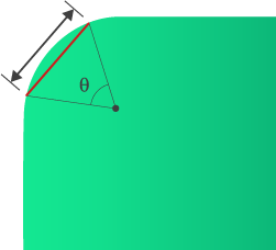
- Chord length
- Rounded features are modeled using straight cords that approximate the curve. The tighter the curve the shorter the cord length needed to accurately represent the feature. The chord length around a curve can be adjusted on the Curves tab of the Generate Mesh tool ()
- Local mesh density
- Prior to meshing the model, use the Define Mesh Density tool () to define a local surface edge length and chord angle. Increasing the mesh density will improve the analysis accuracy but will also increase run time.
- Remesh area
- Remesh Area tool
 () allows you to alter the mesh density of a specified area. Increasing the mesh density will improve the analysis accuracy but will increase run time.
- Match ratio (Dual Domain only)
- In a Dual Domain analysis, the polymer characteristics through the thickness of the part are calculated between matched nodes on opposite faces of the part. Use the Imprint tool to improve the number of matched nodes and hence the accuracy of the analysis.
- Manual mesh editing
- Manual mesh editing of minor features can take considerable time and introduce unexpected mesh errors. Where possible it is recommended to repair the model in the CAD package it was designed in and then import and mesh the modified part.
3D mesh parameters
In general, it is not recommended to repair a 3D mesh. A poor mesh is best repaired by reviewing the CAD model and repairing the model in the CAD package and then re-importing and meshing the part. If this is not possible, import the part as a Dual Domain model and repair the surface mesh. When the Dual Domain mesh is satisfactory, re-mesh the part with a 3D mesh.
When meshing a part in 3D, consider the following:
- Gate mesh refinement
- Mesh refinement around the gate enables the shear forces, temperatures, flow, etc. in this critical area to be more accurately calculated. If an injection location is defined prior to meshing, a refined mesh is automatically generated around the gate. When the injection location is set after the mesh, you will need to re-mesh the part to obtain this feature.
- Maximum Dihedral angle
- The dihedral angle is the angle between the faces of the tetrahedra that make up the mesh. This angle should be less than or equal to 178, but the lower the better. A high angle corresponds to a nearly flat tetrahedral element which cannot accurately reflect the 3D nature of the part.
- To check your model, click
 (). The Mesh Repair Wizard can help reduce this angle.