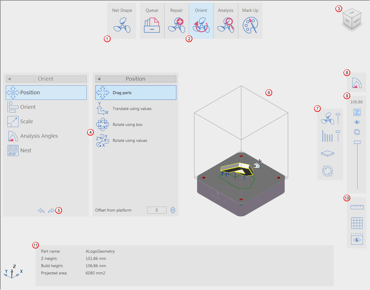
When you have created or opened a project, the user interface contains the following features:
|
Area |
Description |
|---|---|
|
|
Use the Select Mode button to choose between the Net Shape, Subtractive, Additive, and Manufacturing modes. |
|
|
The Main toolbar contains the tools available for the selected mode. |
|
|
The ViewCube shows the current viewpoint of the Graphics window. When you re-orient the view using the mouse, the ViewCube automatically rotates to reflect the new viewpoint. You can also use the ViewCube to manipulate the view directly. |
|
|
The active panels list the options available for the selected tool. |
|
|
Use the Undo and Redo buttons to cancel the last action and redo the previous undo. |
|
|
The Graphics window lets you view the part, platform, and fixtures. |
|
|
Use these toolbar buttons to control the visibility of parts, fixtures, contact points, and the platform. |
|
|
Use these toolbar buttons to analyse parts, show undercuts, and compare the net shape with the near-net shape. |
|
|
Use these toolbar buttons to control the cross-sectional view of parts and fixtures. |
|
|
Use these toolbar buttons to measure distances, display a secondary view, and to control the display of dimensions and the grid on the platform. |
|
|
Depending on the selected tool and options on the active panels, the bottom toolbar is displayed and contains additional options and details. |


