Transpose surfaces, and adjust the surrounding, or extend it with new triangles as needed
- If not already opened, click
Prepare >
 Repair Part to enter the repair module.
- Select the triangles or surfaces to be extruded.
- From the toolbar, click
 Extrude Surfaces.
Tip: You can also access this command from the Mesh Edit menu or right-click the selection and choose Extrude Surfaces.
Extrude Surfaces.
Tip: You can also access this command from the Mesh Edit menu or right-click the selection and choose Extrude Surfaces.
Initially, the surface is extruded a distance of 1 mm normal to the surface. The extruded surface is colored gray.
- Click and drag the gray colored surface to adjust the extrusion height and angle as necessary, or use the
Shift slider.
Tip: Hold the Shift key while moving the surface to lock the extrusion distance and only adjust the direction. Hold the Ctrl key while moving the surface to lock the direction and only adjust the extrusion distance. Double-click any triangle on the part to align the extruded surface parallel to the clicked triangle. Double-click the triangle again to invert the extrusion by 180°. The same behavior occurs if you double-click on an edge in the part.
- Enable one of the following extrusion types:
- Real Extrusion: Creates new triangles to create the extrusion.
- Move Points: Moves the points of the selected triangles, rather than creating new triangles.
- If necessary, you can use the Direction text fields in the context view to fine tune the vector along which the surface is extruded. Click Estimate Direction to align the extruded surface with the average orientation of all selected surfaces.
- Click Apply to complete the extrusion.
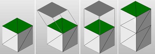
Extrusion: 1) Select a surface. 2) Click and drag the surface. 3) Double-click the original surface to align the extrusion. 4) Apply the extrusion.
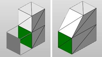
With the Move Points option enabled, the corner points are drawn outward, adjusting the shape of all adjacent triangles.