Add, move, or delete junctions and beams
- To Select Lattice Elements
- To Move and Delete Existing Lattice Elements
 To Modify the Thickness of Beams
 To Add New Beams
-
To Collapse Beams
For editing lattices, a number of functions is available. To show that you are currently editing a lattice, it is displayed in light blue, as opposed to dark green.
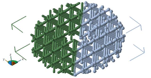
The light blue display color (on the right) of a lattice body indicates that its junctions and beams can be edited individually.
- To begin editing lattices, select the lattice to be edited, then, in the context view, click Edit lattice.
- To finish editing, click Done in the context view.
Editing a lattice is only a temporary state. You can enter and exit editing at any time. Also, editing or clicking Done after editing does not void or clear any undo states that happened before or during editing, so you can undo and redo even individual edits such as placing or moving beams, collapsing junctions, and so on.
To Select Lattice Elements
For the selection of beams and/or junctions using the mouse, a selection of filters is provided in the toolbar that can be used to restrict which type of those elements are selectable.
 Select beams and junctions
 Select beams
 Select junctions
 Select connected clusters
There is also the option to select lattice beams by a property, and for each property you can specify a range. Any beams that meet this range will be selected upon clicking
Select range.
- by length
- by angle from vertical
- by thickness
Finally, there is the option to add the beams found through the search by property to an existing selection, allowing a composite selection. Or, just click
Select all as a shortcut to ignore any selection filters and to select all the beams..
To Move and Delete Existing Lattice Elements
Individual junctions and beams of a lattice can be moved or deleted.
- In the display, make your selection of junctions and beams as needed. Alternatively, use the selection tools in the context view.
- Specify the distance of translation using the
X, Y, and Z input fields in the
context view to move the selected junctions, or click
Remove to delete the junctions including the beams that terminated in them.
Tip: Click and drag the three-axis handle by its arrow tips or its planes to the desired position in the display, and use the Delete key to delete them.
To Modify the Thickness of Beams
Thickness can be adjusted using a numerical input field that also has up and down arrows.
- In the display, make your selection of beams as needed. Alternatively, use the selection tools in the context view.
- Specify the new
thickness. The change is immediate.
Tip: If you have one or more ranges of thicknesses selected, and you use the up and down buttons, the beams will be thickened or thinned relative to their current thickness.
To Add New Beams
Beams can be added as extension to open beams, between selected junctions, or even between selected junctions and beams.
To add a new beam to a junction:
- Select a junction.
- Click Add.
This adds a beam. Netfabb will attempt to put the beam in free space as far away from all other beams attached to the original junction.
To add an extension:
- Select a junction at the end of an open beam.
- Click Add.
The extension will be added as a copy of the open beam.
To add a beam between junctions:
- Select two junctions.
- Click Add.
To Collapse Beams
Collapsing beams deletes all selected beams and connects the involved junctions with beams that converge in a new, single junction at the geometric center of those junctions. In addition, care is taken to avoid duplicate beams and to select the right thickness of the beam ends.
- Select at least one beam.
- In the context area, click Collapse.