Generate and modify lattice structures and part walls with individually configurable tools and methods
- What is it?
- When should I use it?
- What are its key features?
- Where and what are the main controls of Lattice Commander?
What is it?
 Lattice Commander provides convenient access to creating regular, repeating structures to fill interiors or form skin structures natively within
Netfabb. It provides easy and logical tools to start with a solid part and derive the hollowed part and the matching lattice structure or structures from that.
Lattice Commander provides convenient access to creating regular, repeating structures to fill interiors or form skin structures natively within
Netfabb. It provides easy and logical tools to start with a solid part and derive the hollowed part and the matching lattice structure or structures from that.
Use Lattice Commander to generate complex lattice structures within a part or along its surface, and to generate skins around a part to create new designs by combining multiple lattices and skins. Moreover, you can post-process lattices from 3S, or finalize components from Autodesk® Optimization Utility for Netfabb®, before exporting your designs to a workspace and proceeding with slicing and printing.
Lattice Commander requires a Netfabb Premium or Ultimate subscription.
Lattice Commander is a module. calculation results which generates the actual part.
When should I use it?
Lattice Commander is well suited for tasks when manual configuration, generation, and editing of latticed volumes and skins is required, and also when multiple lattice and skin regions are to be manage simultaneously.
However, if you need even more granular and exact control about lattice generation, you should consider using Selective Space Structures instead.
What are its key features?
- Generate lattices and surface lattices from meshes.
- Generate skins from meshes.
- Manage multiple shells and skins simultaneously.
- Edit and trim lattices and skins manually.
 Trim a lattice using a sacrificial mesh.
- Snap separate lattices together.
- Generate a thickness gradient on a lattice.
- Generate the final part directly from the elements created in a component in a one-button-click manner.
- The Lattice Commander's state is saved in the FABBPROJECT file.
Where and what are the main controls of Lattice Commander?
- Using the
main menu, Lattice Commander can be found at
Modify > Lattice Commander.
- The
project tree holds all loaded and created elements, grouped and branched appropriately. There are several types of elements:
-
 A
component represents a working set of
meshes,
skins,
lattices, and
surface lattices. Multiple components can be loaded at once, they are independent and do not interfere with each other. The elements inside a component are called
bodies.
A
component represents a working set of
meshes,
skins,
lattices, and
surface lattices. Multiple components can be loaded at once, they are independent and do not interfere with each other. The elements inside a component are called
bodies.
 An actual
mesh.
An actual
mesh.
 A
skin is the dataset of a mesh where its triangles have received a thickness property. Effectively, a skin is a hollowed part.
Note: A skin is not a mesh, but you can turn it into one.
A
skin is the dataset of a mesh where its triangles have received a thickness property. Effectively, a skin is a hollowed part.
Note: A skin is not a mesh, but you can turn it into one. A
lattice is the dataset of a volume-filling beam structure. The mesh's shape will be sectioned into cells of a given
unit size. Each cell will then be filled by a repeating beam structure of the selected
unit topology.
A
lattice is the dataset of a volume-filling beam structure. The mesh's shape will be sectioned into cells of a given
unit size. Each cell will then be filled by a repeating beam structure of the selected
unit topology.
- A
surface lattice is the dataset of a structure derived from a mesh's wireframe.
Note: Lattices and surface lattices only differ in how they were generated. Other than that, there is no difference between them, in that they are both assemblies of beams and junctions.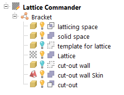
A component named Bracket with a number of bodies comprising it
-
- The
context view holds information and functions applicable to the current selection within
 Lattice Commander. There are three tabs,
Lattice Commander,
Component, and
Body.
Lattice Commander. There are three tabs,
Lattice Commander,
Component, and
Body.
- Generate lattices, surface lattices, skins, switch to editing these bodies, and convert them back to meshes
-
Load components them from a 3MF file or a built-in selection of examples
- Generate a part from the bodies belonging to a component with a single button click
- Perform selections by beam property such as length, and configure selection tools
- Determine the
role of a body:
The role specifies how a body is handled when a part is generated. Bodies can be
 solid, meaning that they will appear in the final output. Mesh bodies can also be used as stencils, inside or outside of which lattices are kept or eliminated (
 trimming and
 voiding, respectively). And of course, they can be set to be
 ignored.
- Preview the part assembly: This assigns colors to the bodies of the component based on their roles.
The context view also provides controls what to do with the original body whenever you are about to perform a function that creates a new one:
- Keep: Keeps the old body in the tree. Helpful for when you want to perform more actions based on this body later.
- Hide: When the original body is kept, it can be switched from
 visible to
 invisible.
-
Exclude from part output: When the original body is kept, it is set to be
ignored from the part output.
- The
display holds the graphical representation of the component and its bodies. Together with the
clip planes,
Netfabb's camera controls via
perspective and
focus controls in the
toolbar and the
mouse controls, it allows visual examination of your latticing work.
Each type of body is colored depending on its type (whether it is a mesh or a skin, for example) and its state (being viewed, previewed, or edited).
For aligning the unit cell grid against the mesh and for moving elements of a lattice, a special control element becomes available: This three-axis handle can be dragged by its arrow tips as well as the planes to move it along an axis or a plane between two axes, respectively.
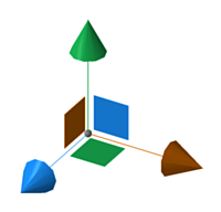
This handle helps with translation with the mouse by aligning the movement with the cardinal axes and planes, independent from the current camera perspective.
Finally, Lattice Commander does
not have any configuration in
System >  Settings.