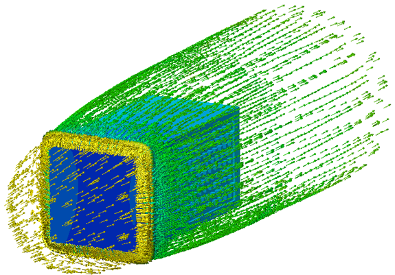
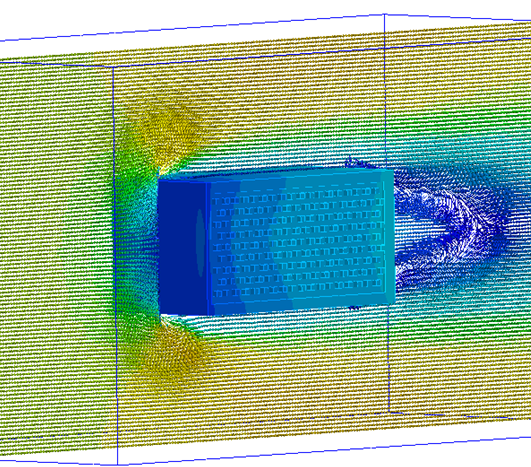
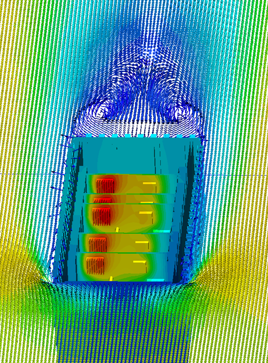
In some applications, a device with forced cooling is subjected to appreciable external cooling effects. A fan inside the device provides component cooling, but a high-speed (incompressible) flow around the device convects heat from the exterior of the enclosure. In the other forced-cooling applications, this effect is either neglected or simulated with a film coefficient boundary condition. In this application, the heat transfer from the exterior of the enclosure is modeled with an air volume that surrounds the device.
Applications

- Power supplies
- Inverters
- Telecommunications devices
- Control modules
- Computing hardware
Modeling Strategy
A volume surrounding the device must be constructed. In some cases the surrounding volume is a physical structure, such as a wind tunnel. In other cases, the device is in either a very large room or an open environment:
- Add this volume either in the CAD model or in Autodesk® CFD with theExternal Volume tool.
- If the device is in a wind-tunnel, use the same dimensions as the wind-tunnel.
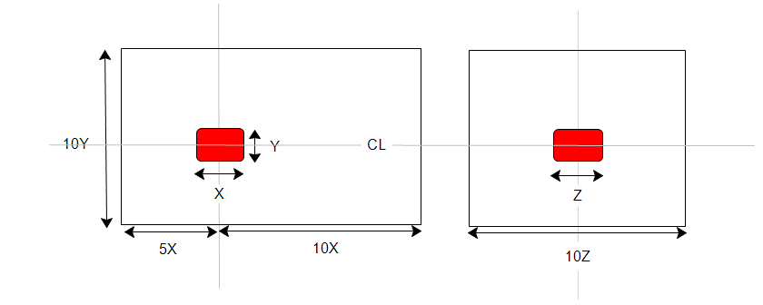
- If the wind-tunnel is larger than five times the size of the device, or if the device is located far from physical boundaries, use these enclosure sizes:

The device can either be sealed or vented. If sealed, air within the device is separated from the surrounding volume. If vented, air in the surrounding volume passes around as well as through the device.
Materials
- The properties of air should be constant.
- Assign Air, and set the Environment setting to Fixed.
- For very thin enclosures, the heat transfer is largely dominated by thermal conduction instead of convection. In certain applications, it is possible to accurately simulate the heat transfer without having to solve for the flow. A solid material called Solid Air, in the Default database, has the thermal properties of air. For more about using the Solid air material...
- Use material devices to simulate objects such as baffles, internal fans, printed circuit boards, compact thermal models, and thermal electric devices. For more about using material devices...
- Use aluminum or other appropriate material for housing parts.
Boundary Conditions
- To define the inlet of the air volume, assign Velocity or Volume Flow Rate.
- To define the outlet of the air volume, assign Static Gage Pressure = 0.
- If the air region simulates a free-space environment (not a wind-tunnel), assign Slip/Symmetry to the sides of the region.
Heat transfer boundary conditions should always be applied if the objective is to learn the temperature distribution. (These can be omitted if the objective is to assess only the flow.)
- Apply a Temperature boundary condition to inlet of the air volume. Do not apply a temperature to outlets.
- Apply a Total Heat Generation boundary condition on components that dissipate heat. Note that power is evenly dissipated over the entire volume.
- If the air volume acts as a cold plate, specify a Temperature or Film Coefficient boundary condition. Otherwise, leave the sides unspecified.
- If solar heating is a consideration, either specify a Heat Flux boundary condition on the surfaces of the air volume or enable Radiation and Solar heating on the Solve dialog.
Mesh
A basic guideline for a high-quality analysis model is that the mesh distribution be sufficient to resolve the flow and temperature gradients efficiently. In regions where the flow circulates or experiences large gradients (such as in wakes, vortices, and separation regions), a finer mesh is required.
For most models, use Automatic Sizing to define the mesh distribution. It may be necessary to locally refine the mesh on geometric features that are highly detailed. For more information about Mesh Autosizing and model preparation...
In some cases, it may be necessary to adjust the Minimum Refinement Length to reduce their effect on the overall mesh count.
To locally refine the mesh in high-gradient flow regions:
- Adjust the mesh distribution on geometric volumes and surfaces.
- If there are no appropriate geometric features in a particular region, create a mesh refinement region:
- Add one or more volumes in the CAD model.
- Create a Refinement Region from the Meshing task.
Running
On the Physics tab of the Solve dialog:
- Flow = On
- Heat Transfer = On
- Automatic Forced Convection = On
- Turbulence:
- Most forced-flow analyses are turbulent, and the default model, K-Epsilon, is recommended.
- Flow in devices with a "puller" fan may be laminar. To select Laminar on the Turbulence dialog:
- Open the Solve dialog, click the Physics tab, and click the Turbulence button. Select Laminar.
Autodesk® CFD stops the solution either when the specified number of iterations have elapsed or when the solution is converged, whichever comes first. To ensure the analysis is not stopped before converging, set the Iterations to Run to 500. Most analyses converge within 200-300 iterations so 500 should provide an adequate margin.
Results Extraction
Flow Distribution

Component Temperatures

- Use Results Planes and Iso Surfaces to visualize the flow in and around the fixture.
- Use Particle traces to visualize air movement.
- Display temperature directly on parts and use Results Parts to extract quantitative temperature data.
- Use the Decision Center to compare results from multiple scenarios. Save summary images and create summary items, and evaluate the results in the Critical Values table.
For more general information, use the extensive collection of results visualization tools to extract flow and thermal results.
Things to Avoid
- Do not include geometric detail that is irrelevant to the flow and heat transfer. Remove features such as sheet metal bends, screws, and wires.
- Flow and heat transfer can be solved simultaneously, but this usually takes longer than solving them in series (either manually or with Automatic Forced Convection).
- The only time it is necessary to solve flow and heat transfer together is if the air properties vary with temperature.
- Do not specify flow conditions directly on the device.
- In most cases, a temperature boundary condition should not be specified on the device.