Learn how to modify the provided reinforcement area due to exceeding the deflection.
- Continue working in your project or open the project Plate_Provided_Reinforcement_Verification.rtd.
Note: The Tutorial files are located in C:\ProgramData\Autodesk\Examples\Tutorials.
- To display the provided reinforcement maps, go to the Plate and Shell Reinforcement dialog, and in the Results for a rectangle mesh group click
 (Rectangular reinforcement map), and make sure that Provided reinforcement Ar is selected.
 - Go to the Bending tab, and select a Manual definition of the Reinforcing zone.
The Bars table of reinforcement bars is enabled. We use this table to modify the reinforcement parameters.
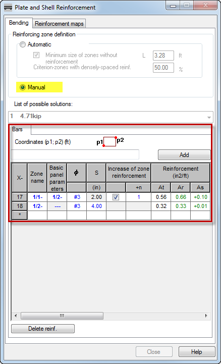
- Click
 (the last row in the table) to add a new zone.
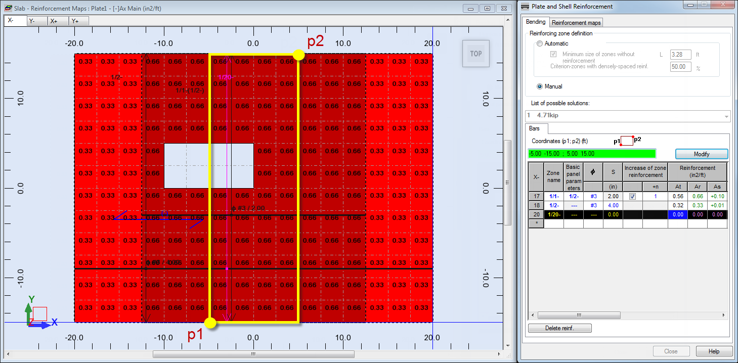
The row is highlighted in black.
- Place the cursor in the Coordinates (p1 ; p2) box.
The Coordinates box is highlighted in green.
- Enter the following coordinates:
- (-5.00 -15.00 ; 5.00 15.00), and click Add.
Alternatively, you can select these points in the drawing area: p1 (-5.00 -15.00) and p2 (5.00 15.00). Ensure that the Coordinates box is highlighted in green before you select the points.
The new 1/20- zone appears in the view.
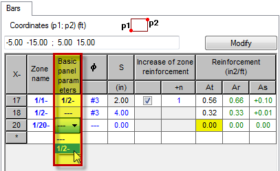
- To set the basic panel for the zone 1/20-, do the following:
- Go to row 20,
- Select 1/2- zone in the Basic panel parameters, and then press Enter.
- To set the bar diameter for the zone 1/1-, do the following:
- Go to row 17,
- Select #7 in the Φ column, and then press Enter.
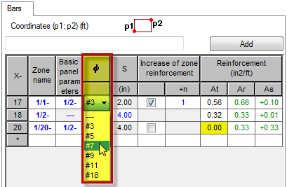
- Repeat the step 8 for the zone 1/2-.
This changes the bar diameter for the zones 1/2- and 1/20-.
- To set the bar spacing for the zone 1/2-, do the following:
- Go to row 18,
- Select, or type 10.00 in the S column, and then press Enter.
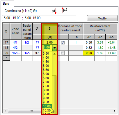
Note: This changes the bar spacing for all zones. - To increase the zone reinforcement and the bar spacing for the zone 1/20-, do the following:
- Go to row 20,
- Select the Increase of zone reinforcement option,
- Select 2:3.33 from the +n column, and then press Enter.
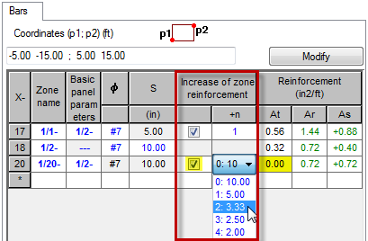
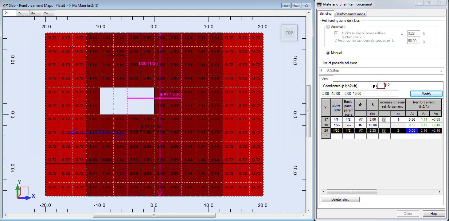
- The modified bottom provided reinforcement area for the X direction looks as shown below:
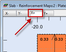
- In the top left corner of the Slab - Reinforcement Maps view select the X+ tab.
The top provided reinforcement area for the X direction display in the view.
- Click
 (View
(View  Zoom
Zoom  Zoom All) to better visualize the defined plate.
Tip: To refresh the reinforcement map displayed on the drawing click View
 Redraw.
 - Go to the table and select row 2 (1/2+ zone).
The row is highlighted in black, also the 1/2+ zone is highlighted in pink in the view.
- Press the Ctrl key on your keyboard, and then select rows 3, 4, 5, 6 and 7 (zones 1/3+, 1/4+, 1/5+, 1/6+, and 1/7+).
The rows are highlighted in black, also the zones 1/3+, 1/4+, 1/5+, 1/6+, and 1/7+ are highlighted in pink in the view.
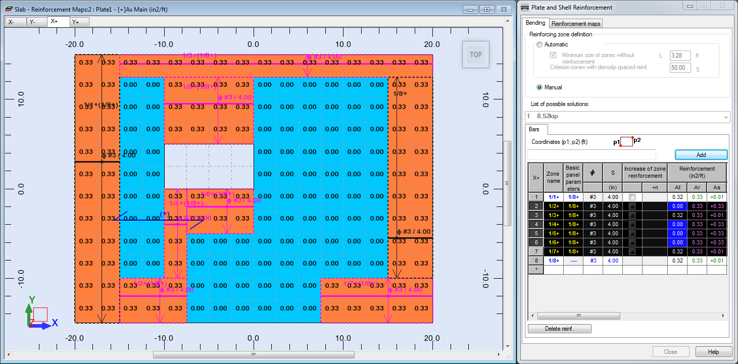
- Press the Delete key on your keyboard to delete the selected zones.
Tip: If you want to delete the generated reinforcement only, i.e. not the zone, click Delete reinf at the bottom left corner of the Plate and Shell Reinforcement dialog. This deletes reinforcements for all zones and for all directions.
- Select row 2 (zone 1/8+).
The row is highlighted in black, and the zone 1/8+ is highlighted in pink in the view.
- Place the cursor Click in the Coordinates (p1 ; p2) box.
The Coordinates box is highlighted in green.
- Enter the following coordinates:
- (15.00 -15.00 ; 20.00 15.00), click Modify.
Alternatively, you can select these points in the drawing area: p1 (15.00 -15.00) and p2 (20.00 15.00). Ensure that the Coordinates box is highlighted in green before you select the points.
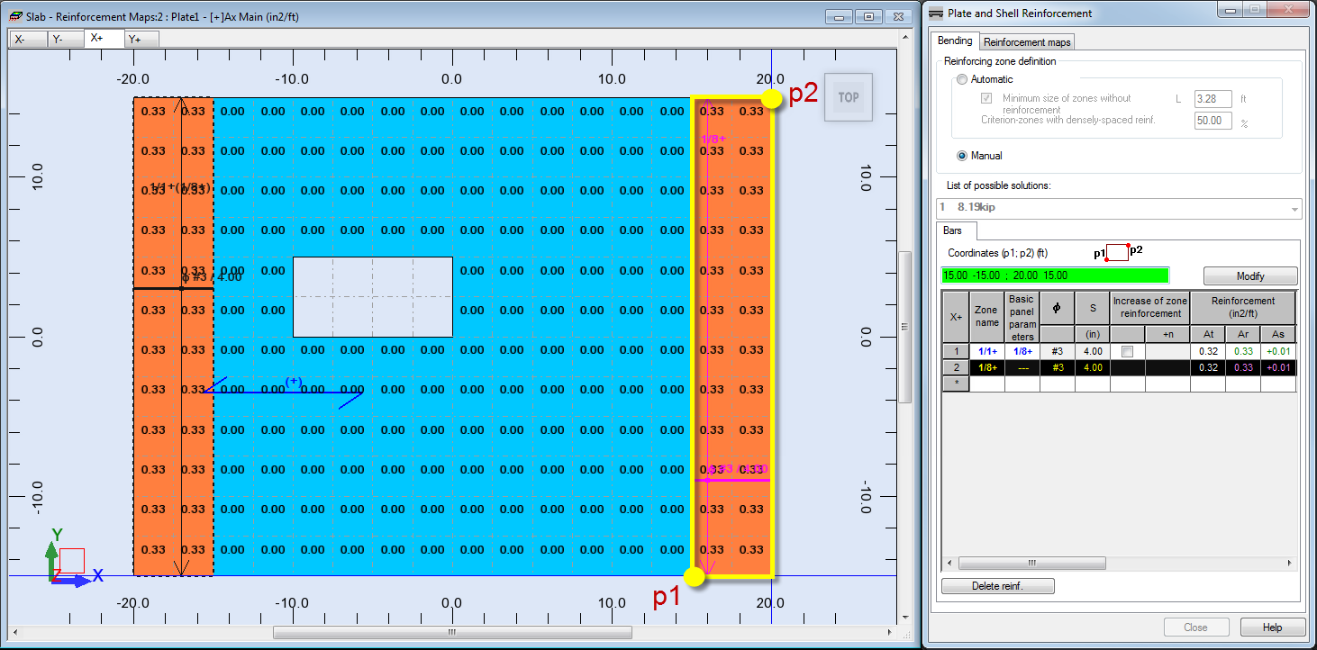
- Click
 (the last row in the table) to add a new zone.
The row is highlighted in black.
- Place the cursor in the Coordinates (p1 ; p2) box.
The Coordinates box is highlighted in green.
- Enter the following coordinates:
- (-20.00 -15.00 ; 20.00 15.00), click Add.
The new 1/15+ zone appears in the view.

- To change the name of the zone 1/8+, do the following:
- Go to row 2,
- Type 1/2+ in the Zone name column, and then press Enter.
- To set the reinforcement parameters for the zone 1/15+, do the following:
- Go to row 15,
- Type 1/3+ in the Zone name column, and then press Enter,
- Select #3 in the Φ column, and then press Enter,
- Select, or type 6.00 in the S column, and then press Enter.
- To set the reinforcement parameters for the zone 1/1+, do the following:
- Go to row 1,
- Select 1/3+ in the Basic panel parameters,
- Select the Increase of zone reinforcement option,
- Select 2:2.00 from the +n column, and then press Enter.
- Go to row 2, and then repeat step 26 for the zone 1/2+.
- The modified top provided reinforcement area for the X direction looks as shown below:
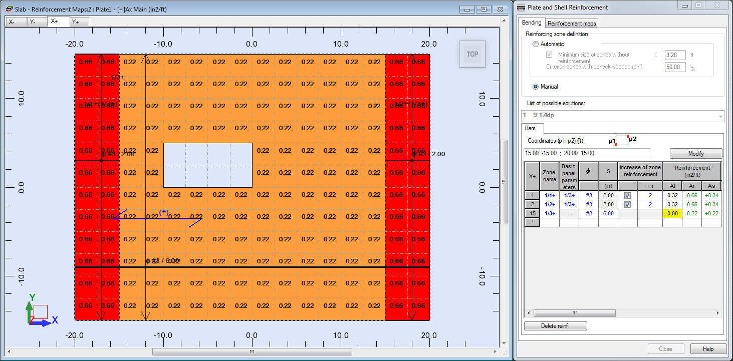
- Save the project as Plate_Provided_Reinforcement_Modification.rtd.