Learn how to define the plate contour with the opening.
- Continue working in your project, or open the project Plate_Preferences.rtd.
Note: The Tutorial files are located in C:\ProgramData\Autodesk\Examples\Tutorials.
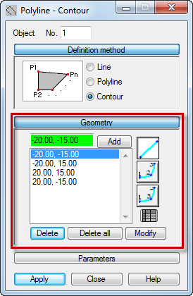
- Click Geometry
 Objects
  Polyline - contour.
The Polyline - Contour dialog opens.
- Ensure that Contour is selected in the Definition method group.
- Click Geometry.
The geometry edit box appears in the dialog.
- To create a plate contour, enter the following point coordinates:
- (-20.00, -15.00), click Add, Important: The coordinate's syntax depends on your regional Windows format. In this tutorial, we use the English (United States) format. If you want to change your Windows format, click: Start
 Control Panel
  Region and Language
  Format.
 - (-20.00, 15.00), click Add,
- (20.00, 15.00), click Add,
- (20.00, -15.00), click Add,
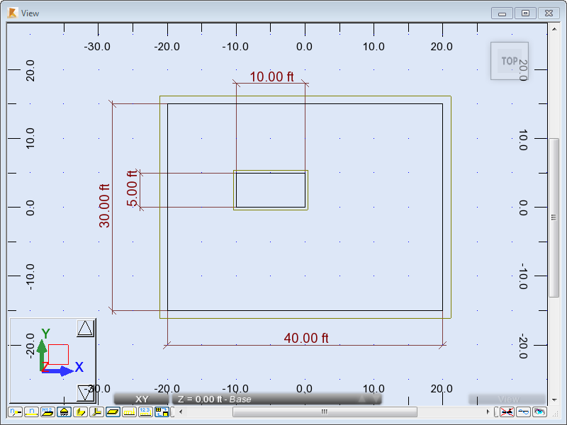
- (-20.00, -15.00), click Add. Note: Once you enter the first set of coordinates again, the contour is complete and appears in the drawing area.
Alternatively, you can place the cursor in the Geometry edit box and select the coordinates in the drawing area.

- (-20.00, -15.00), click Add,
- To define an opening, enter the following point coordinates:
- (-10.00, 0.00), click Add,
- (-10.00, 5.00), click Add,
- (0.00, 5.00), click Add,
- (0.00, 0.00), click Add,
- (-10.00, 0.00), click Add. Note: Once you enter the first set of coordinates again, the contour is complete and appears in the drawing area.
Alternatively, you can place the cursor in the Geometry edit box and select the coordinates in the drawing area.
 Tip: To add the dimension lines, click Tools
 Dimension Lines. For more information about the dimension lines available in Robot, see Dimension Lines.
 - Close the Polyline - Contour dialog.
- Click
 (View
(View  Zoom
Zoom  Zoom All) to better visualize the defined contour.
 - Save the project as Plate_Contour.rtd.