Learn how to set the calculation options and how to start the calculations of the provided reinforcement area.
- Continue working in your project or open the project
Plate_Required_Reinforcement_Tabular.rtd.
Note: The Tutorial files are located in C:\ProgramData\Autodesk\Examples\Tutorials.
- Click
 (Window
 Inspector Dialog Box).
The Object Inspector opens.
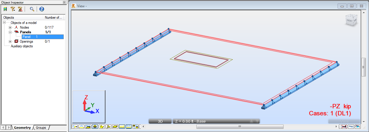
- Go to the Object Inspector, expand the
Panels list, and then select
Panel 1.
The plate is highlighted.

- Click
 (Design
  Provided Reinforcement of RC Elements).
The Slab - provided reinforcement layout opens. The layout is divided in two parts: Slab - Reinforcement Maps view, and Plate and Shell Reinforcement dialog.
- Click
 (View
(View  Zoom
Zoom  Zoom All) to better visualize the defined plate.
- Click
 (Analysis
  Reinforcement Pattern).
The Reinforcement Patterns - ACI 318-11 dialog opens.
- In the General tab, select Bars as Reinforcement type.
- Go to
Constructional reinf. tab, and deselect
 .
.
- Click OK.
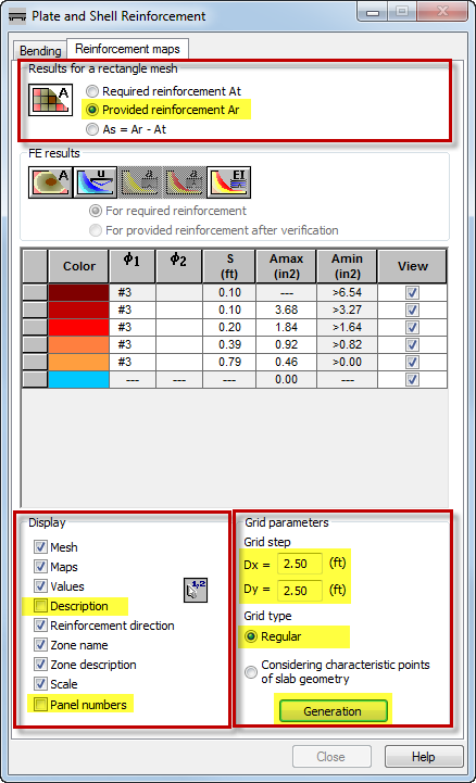
- To display the provided reinforcement maps, go to the Plate and Shell Reinforcement dialog. Click the Reinforcement maps tab, and then in the Results for a rectangle mesh group select Provided reinforcement Ar.
- To improve the visibility of the reinforcement maps, go to the Display group, and then deselect Description and Panel numbers.
- To adjust the grids of the reinforcement maps to the plate, go to the
Grid parameters group, and then set the following properties:
- Grid step: Dx=Dy=2.50,
- Grid type: Regular,
- Click
Generation.

- Click
 (Analysis
  Calculations).
The Calculations dialog opens.
- Click
Calculate.
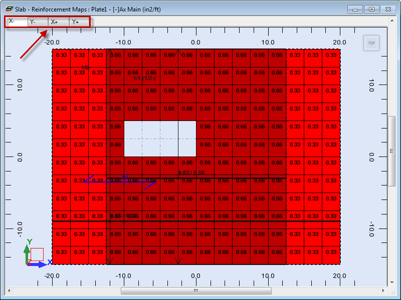
The bottom provided reinforcement area for the X direction displays in the view. To view the reinforcement for other directions, in the top left corner of the screen select another tab e.g. Y-.
 Note: As you can see, the largest amount of the provided reinforcement is located in the middle of the plate, therefore the results are appropriate regarding the opening and the method of plate support.
 - Save the project as Plate_Provided_Reinforcement.rtd.