Use the Model area clearance page to specify settings for a model area clearance roughing toolpath. This strategy creates a toolpath by slicing the model at specified heights and then creating a Raster, Offset or Vortex pass at each height.
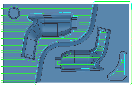
- A Raster style toolpath creates cutting moves at a specified angle to either the X or Y axis. Raster toolpaths are often used on open parts.
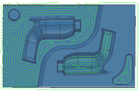
- An Offset model / Offset all style toolpath creates cutting moves by offsetting the model or block. These work well in the bottom of pockets and are good for high-speed machining.
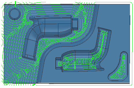
- A Vortex style toolpath produces an offset toolpath which never exceeds the maximum tool engagement angle for optimum machining. As the tool approaches the maximum engagement angle, the toolpath changes to a trochoidal path to avoid tool overload. This works well for solid carbide tools.
Style — Select the style to use for removing material.
- Raster — This comprises straight-line moves parallel to either the X or Y axis.
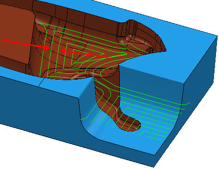
- Offset model — This clears an area with contours generated by repeatedly offsetting the initial slice until no further offset is possible.
This produces a toolpath that:
- maintains constant tool load and chip production.
- maintains cut direction.
- avoids machining small or thin-walled upstands.
- minimizes full-width cuts.
This option increases the number of tool lifts.
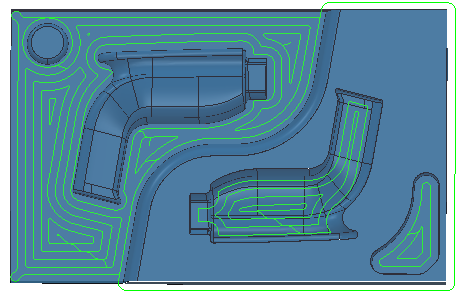
- Offset all — This produces an offset toolpath which minimizes the number of tool lifts and works extremely well for soft materials.
- Vortex — This produces an offset toolpath which never exceeds the maximum tool engagement angle for optimum machining. As the tool approaches the maximum engagement angle, the toolpath changes to a trochoidal path to avoid tool overload.
Cut direction —Select a particular milling style for Profile and Area.
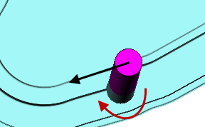
- Climb — Select to create toolpaths using only climb milling, where possible. The tool is on the left of the machined edge when viewed in the direction of tool travel.
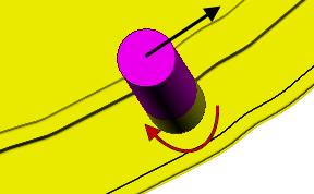
- Conventional — Select to create toolpaths using only conventional or upcut milling, where possible. The tool is on the right of the machined edge when viewed in the direction of tool travel.
- Any — Select to create toolpaths using both conventional and climb milling, as appropriate. This minimizes the tool lifts and tool travel.
Tolerance — Enter a value to determine how accurately the toolpath follows the contours of the model.
Thickness — Enter the amount of material to be left on the stock within tolerance. Thickness is applied as an offset to the tool in all directions:
Stepover — Enter the distance between successive area clearance passes at a single height.
Stepover with a Style of Offset model:
Stepover with a Style of Raster:
Stepover with a Style of Vortex:

Stepdown — The Automatic option is selected to specify that the Stepdown value you enter defines the distance between different machining levels.