Cutting limits define the area in which all cutting moves occur when machining a Turning toolpath.
To display the cutting limits for a profile group, select Part Features > Show Cutting Limits. To hide the cutting limits for a profile group, select Part Features > Hide Cutting Limits.
The cutting limit is displayed as a thick line, drawn in the same color as the group for which it is defining the cutting area.
You can define cutting limits in the following ways:
- By Cutting Point
Defining cutting limits by the Cutting Point creates a rectangular cutting area drawn from the cutting point (see
 ) to the part profile (see
  ). The boundaries of the cutting area (see
 ) are formed by an intersection of straight line segments drawn from the cutting point to the defined part profile. These lines must intersect the defined part profile.
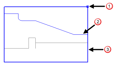
- By Part Profile Boundaries
Defining cutting limits by the part profile creates a rectangular cutting area (see
) around the part profile (see ). The boundaries of the cutting area are drawn out from the end points of the defined part profile.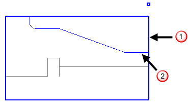
- By Stock Profile Boundaries
Defining cutting limits by the stock profile enables you to define a non-rectangular cutting area. PartMaker creates a rectangle around the defined stock profile (see
), and the boundary of the cutting area is then defined by the stock profile boundary and the remaining sides of the rectangle. In the following example, the cutting area is shown colored in.