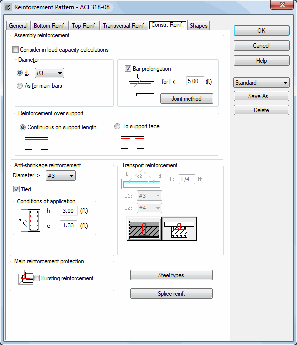
Once the Reinforcement Pattern command is called up and the Structural Reinforcement tab is selected, the dialog box shown below will appear on the screen.

The above dialog box contains options which facilitate the definition of the following types of structural reinforcement:
- Anti-shrinkage reinforcement. This reinforcement is to limit cracks in concrete, to counter possible twisting or bending moments in relation to the section height. An additional function is to straighten the reinforcement skeleton. The user may assign the reinforcement diameter or select the AUTO option. In this case, the program will select the optimal diameter on its own on the basis of code recommendations. Additionally, it is possible to define the near surface reinforcement use criteria dependent on the beam height and the maximal spacing between the reinforcement bars.
- Transport reinforcement. Pertains to prefabricated beams and functions as reinforcement necessary during transport of the prefab members. Once the Steel Type button is pressed the additional dialog box opens in which a steel type for a particular reinforcement type may be defined.
- Assembly reinforcement is negligible in calculations. It is used mainly to suspend and tie the transversal reinforcement. It may be defined by selecting its diameter from the list or be dependent on the diameter of main reinforcement bars. If this reinforcement should be taken into account in the capacity calculations, then the Consider in load capacity calculations option should be switched on. The Bar Prolongation for L < option refers to the assembly reinforcement; switching this option on imposes prolongation of main bars (joining the neighboring main bars) and giving up bars of the assembly reinforcement if the assembly bar length is smaller than the defined length 'l'. The assembly bar length is considered as a theoretical length (without anchors), i.e. this is a theoretical segment along which the main reinforcement is not required (between points with the zero value in a diagram of the required reinforcement area). It should be emphasized here that the option allowing prolongation of main bars is of importance only when the Whole beam option on the General tab is selected as a reinforcement segment (otherwise, bars of the main reinforcement assigned to different segments cannot be joined with each other and the assembly reinforcement is generated between them).
- Main Reinforcement Protection. Activation of this option results in generating the reinforcement on edge supports, having a strengthening effect on the main bar anchorage and preventing hook bending and the splitting of concrete. In the case of bars ending in hooks, it occurs at a 90 degree angle.
- Steel type as for longitudinal/ transversal reinforcement. This option allows determining a steel type for all structural reinforcement elements except transport reinforcement, for which a steel type is defined separately. If the Consideration of Load Capacity option is switched on for the assembly reinforcement, then there should be set an identical steel type as in case of longitudinal reinforcement. Otherwise, the calculations may be incorrect.
The bottom part of the dialog box contains the Splice reinforcement button. Pressing the button results in opening the dialog box that allows one to define the shape, diameter, or spacing of the splice reinforcement in a T-section beam.
Note: It makes sense to use the Splice reinforcementoption only in the case of T-section beams.