The Edit UVWs dialog menu bar provides access to a number of important editing commands. Some of these commands are replicated on the dialog toolbar and the Unwrap UVW command panel; others, such as the Mapping, Stitch, and Sketch tools, are available only from the menus.
Interface
File menu
- Load UVs
-
Loads a previously saved UVW (texture coordinates) file.
- Save UVs
-
Saves the UVW coordinates to a UVW file.
- Reset All
-
Restores the UVW coordinates to their original status.
Reset All has almost the same effect as removing and reapplying the modifier, except that a map assigned in the Edit UVWs dialog is not deleted. For example, if you forgot to turn on the Generate Mapping Coordinates checkbox for an object, and then applied the Unwrap UVW modifier, the modifier would have no UVW coordinates to use and its settings would be wrong. If you then go back in the modifier stack and turn on Generate Mapping Coordinates, you'd need to choose the Reset All command. When you do so, an alert warns you that you're losing any edits you've made.
Edit menu
These commands provide access to the different transform functions, and copy and paste selections.
- Copy
-
Copies the current selection (that is, texture coordinates) into the paste buffer.
- Paste
-
Applies the texture mapping coordinates in the paste buffer to the current selection. Using Paste repeatedly with the same target coordinates causes the coordinates to rotate by 90 degrees each time.
Use Copy and Paste to apply the same mapping coordinates (that is, image) to a number of different geometry polygons. A typical example of usage would be in designing a game level, where you're working with a multi-image texture map, part of which is a door image. You might want to apply the same door image to several different door polygons. First, you would select one of the door polys and position it over the door image. Next, use Copy to place its texture coordinates in the paste buffer. Then select another door poly and choose Paste or Paste Weld. The door's texture coordinates move to the same location as the original poly. Continue selecting other door polys and pasting until all the doors are mapped.
Tip: For best results, use comparable sets of texture coordinates for the source and destination. For example, copy a single four-sided polygon, and then paste another four-sided polygon. - Paste Weld
-
Applies the contents of the paste buffer to the current selection and then combines coincident vertices, effectively fusing the source and destination selections together.
Use this function to end up with a single set of texture coordinates that's applied to multiple geometry elements. Adjusting these texture coordinates changes the mapping for all geometry to which they're applied.
- Move Mode
-
Lets you select and move sub-objects.
- Rotate Mode
-
Lets you select and rotate sub-objects.
- Scale Mode
-
Lets you select and scale sub-objects.
- Freeform Gizmo
-
Lets you select and transform sub-objects: vertices, edges and polygons. See Freeform Mode.
Select menu
These commands let you copy a viewport selection to the editor, and transfer selections among the three different sub-object modes.
- Convert Vertex to Edge
-
Converts the current vertex selection to an edge selection and places you in Edge sub-object mode. For an edge to be selected, both of its vertices must be selected.
- Convert Vertex to Polygon
-
Converts the current vertex selection to a polygon selection and places you in Polygon sub-object mode. For a polygon to be selected, all of its vertices must be selected.
- Convert Edge to Vertex
-
Converts the current edge selection to a vertex selection and places you in Vertex sub-object mode.
- Convert Edge to Polygon
-
Converts the current edge selection to a polygon selection and places you in Polygon sub-object mode. For a polygon to be selected, the current edge selection must include all of its vertices. For example, if two opposite edges of a four-sided polygon are selected, the edge selection includes all four of the face's vertices, so this command will select the polygon.
- Convert Polygon to Vertex
-
Converts the current polygon selection to a vertex selection and places you in Vertex sub-object mode.
- Convert Polygon to Edge
-
Converts the current polygon selection to an edge selection and places you in Edge sub-object mode.
- Select Inverted Polygons
-
Selects any polygons facing away from the current mapping. Available only in Polygon selection mode.
This is useful in complex models for finding polygons on a surface that folds in under itself, thus causing potential problems with bump mapping.
For example, add a sphere, turn off Generate Mapping Coords, and them apply Unwrap UVW. This causes the modifier to apply planar mapping from the top down, so that all polygons on the bottom half of the sphere are “inverted”; that is, they face away from the mapping. In the modifier stack display, highlight the Select Polygon sub-object level, and then click the Edit button to open the UVW editor. Choose the Polygon selection mode, and then choose Select
 Select Inverted Polygons. In the viewports, the bottom half of the sphere turns red to indicate that the inverted polygons are now selected.
- Select Overlapped Polygons
-
Selects any polygons that overlap other polygons. If no polygon is selected, this selects all overlapping polygons. If a polygon selection exists, this selects only overlapping polygons within the selection. Available only in Polygon selection mode.
When working with complex meshes, it's common for texture-coordinate polygons to overlap one another, with the result that they use the same portion of the texture map. Use this command to find overlapping polygons in order to separate them as needed.
Tools menu
Tools on this menu let you flip and mirror texture coordinates, weld vertices, combine and separate sets of texture coordinates, and sketch outlines for multiple selected vertices.
- Flip Horizontal/Vertical
-
Detaches the selected sub-objects along their boundary edges and then applies Mirror Horizontal or Vertical, depending on the mode.
- Mirror Horizontal/Vertical
-
Reverses the direction of selected sub-objects along the indicated axis and flips UVs accordingly.
- Weld Selected
- Combines shared vertices and edges belonging to selected sub-objects within the UV-space radius specified by the Weld Threshold setting. Use this to connect separate clusters of texture coordinates.
- Target Weld
-
Combines pairs of vertices or edges by dragging. Not available at the Polygon sub-object level.
Turn on Target Weld, and then drag one vertex to another vertex, or one edge to another edge. As you drag, the cursor changes in appearance to cross hairs when it's over a valid sub-object. While this command is active, you can continue welding sub-objects, and change the sub-object level. To exit Target Weld mode, right-click in the editor window.
- Break
-
Applies to the current selection; works differently in the three sub-object modes. At the Vertex sub-object level, Break replaces each shared vertex with two vertices. With edges, Break requires at least two contiguous edges to be selected, and separates each edge into two. With polygons, Break splits the selection off from the rest of the mesh into a new element, exactly as does Detach Edge Verts.
- Detach Edge Verts
-
Tries to split off the current selection into a new element. Any invalid vertices or edges are removed from the selection set before the detach.
- Stitch Selected
-
For the current selection, finds all the texture vertices that are assigned to the same geometric vertex, brings them all to the same spot, and welds them together. With this tool you can automatically connect polygons that are contiguous in the object mesh but not in the editor.
To use Stitch Selected, first select sub-objects along an edge you want to connect (by default, this causes the shared edges to highlight), and then choose the command. In the Stitch Tool dialog, adjust the settings, and then click OK to accept or Cancel to abort.
- Pack UVs
-
Distributes all texture-coordinate clusters through the texture space using one of two methods and spacing you specify. This is useful if you have several overlapping clusters and wish to separate them.
Choosing Pack UVs opens the Pack dialog.
- Rescale Clusters
- Automatically scales clusters, in place, in proportion to each other. Applies only to two or more clusters with at least one sub-object selected each. If no sub-object is selected, applies to all clusters.
- Sketch Vertices
-
Lets you draw outlines for vertex selections with the mouse. This is useful for matching coordinate cluster outlines to sections of the texture map en masse, without having to move vertices one at a time.
Choosing Sketch Vertices opens the Sketch Tool dialog. Sketch Vertices is available only in the Vertex sub-object mode.
- Relax Dialog
-
Opens the non-modal Relax Tool dialog, which lets you change the apparent surface tension in a selection of texture vertices by moving vertices closer to, or away from, their neighbors. Relaxing texture vertices can make them more evenly spaced, resulting in easier texture mapping. Available at all sub-object levels.
Note: This command, as well as a Relax command that lets you apply the default settings to the current selection without opening the dialog, are available as assignable keyboard shortcuts. - Render UVW Template
-
Opens the Render UVs dialog, which lets you export texture mapping data as an image file that you can then import into 2D paint software.
Mapping menu
Lets you apply one of three different types of automatic, procedural mapping methods to a model. Each method provides settings so you can adjust the mapping to the geometry you're using.
With each method, the mapping is applied to the current polygon selection; if there is no polygon selection it is applied to the entire mesh.
Here's a quick overview of the available methods:
- Flatten mapping prevents overlap of mapping clusters, but can still cause texture distortion.
- Normal mapping is the most straightforward method, but can result in even greater texture distortion than with Flatten mapping.
- Unfold mapping eliminates texture distortion, but can result in overlapping coordinate clusters.
- Flatten Mapping
-
Applies planar maps to groups of contiguous polygons that fall within a specified angle threshold.
Choosing Flatten Mapping opens the Flatten Mapping dialog.
- Normal Mapping
-
Applies planar maps based on different vector-projection methods.
Choosing Normal Mapping opens the Normal Mapping dialog.
- Unfold Mapping
-
Unfolds the mesh so you get no polygon distortion, but does not guarantee that polygons will not overlap.
Choosing Unfold Mapping opens the Unfold Mapping dialog.
Options menu
- Load Defaults
-
Loads the editor settings from the file unwrapuvw.ini in the plugcfg directory.
- Save Current Settings as Default
-
Saves the editor settings to the file unwrapuvw.ini in the plugcfg directory. Settings saved in this way persist between sessions.
- Always Bring Up The Edit Window
-
When on, selecting an object with the Unwrap UVW modifier active automatically opens the Edit UVWs dialog. By default, this is off, so you must click the Parameters rollout
Edit button to open the dialog.
- Preferences
-
Opens the Unwrap Options dialog.
Display menu
- Hide Selected
-
Hides all selected sub-objects and associated polygons.
- Unhide All
-
Reveals any hidden sub-objects.
- Unfreeze All
-
Unfreezes any frozen sub-objects.
Note: You can freeze a sub-object selection with Freeze Selected, available from the right-click menu Display quadrant.
- Filter Selected Faces
-
When on, the editor displays UVW vertices of the viewport selection at the Polygon sub-object level of the modifier, and hides the rest.
This is a quick way to work on a limited selection of the texture coordinates of a complex mesh while ignoring the rest. You can turn this on, go to the Polygon sub-object level of the Unwrap UVW modifier, and select the portion of the object whose texture coordinates you want to edit; only those coordinates appear in the editor, and remain visible even when you change the sub-object level. To work on a different portion, return to the Polygon level and change the selection in the viewport; the editor window updates to the new selection automatically.
- Show Hidden Edges
-
Toggles the display of hidden polygon edges.
- Show Edge Distortion
-
Uses a green-to-red color range to depict distortion: how far in length texture edges are from their corresponding geometry edges. The greater the disparity in lengths (that is, the greater the distortion), the redder the edge appears in the Edit UVW dialog window. Also draws end segments of edges that are too long as white, showing the difference in length from that of the geometry edge.
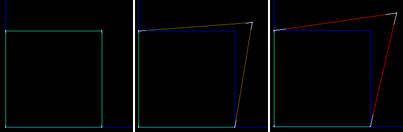
Left: Texture edges the same as or very close to geometry edges in length are green.
Center: Texture edges slightly different from geometry edges in length are brown.
Right: Texture edges very different from geometry edges in length are red.
When texture edges are longer than geometry edges, white end segments depict length disparity.
Use this display as a way to view where the areas of greatest distortion are in your texture mesh. If an edge is brown or red but doesn't have white end segments, it's too short. If it's brown or red and has white end segments, it's too long, by the total length of the white segments.
- Show Vertex Connections
-
In Vertex sub-object mode, toggles the display of numeric labels for all selected vertices. Shared vertices are indicated by the appearance of multiple same-numbered labels.
- Show Shared Sub-objects
-
When turned on, for the current selection, highlights any shared vertices and/or edges. You can change the highlight color on the Unwrap Options dialog.
View menu
- Pan
-
Activates the Pan tool, which lets you move horizontally and vertically in the window by dragging the mouse.
As with the viewports, if you use a three-button mouse, you can also pan by middle-button dragging.
- Zoom
-
Choose Zoom, and then drag downward in the editor window to zoom out and upward to zoom in. Zooming is centered about the point you click before dragging.
If you have a wheel mouse, you can also turn the wheel to zoom. Zooming is centered about the mouse cursor location.
- Zoom Region
-
To zoom to a specific area, choose Zoom Region, and then drag a rectangle in the editor window.
- Zoom Extents
-
Zooms in or out to automatically fit all UVW vertices in the editor window.
- Zoom Extents Selected
-
Zooms in or out to automatically fit all selected UVW vertices in the editor window.
- Zoom To Gizmo
-
Zooms the active viewport to the current selection.
- Show Grid
-
Displays a grid in the background of the editor window. Default=on.
- Show Map
-
Displays a texture map in the background of the editor window. Set the image via the drop-down list at the right end of the editor toolbar.
- Update Map
-
Causes the displayed texture map to reflect any changes to the texture, such as tiling settings or a different bitmap.