The Edit UVWs dialog contains a number of rollouts that provide various tools for editing texture coordinates. Among these are tools for transforming and subdividing UVWs procedurally, thus providing artists with useful shortcuts for more-efficient texture editing.
Interface
The Edit UVWs dialog rollouts are arrayed vertically on the right side of the dialog, and can be opened, closed, and scrolled just like rollouts on the command panels.
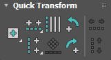
Quick Transform rollout
You can transform UVW sub-objects using the mouse with the tools on the upper toolbar, or procedurally with these tools.
-
 Set Pivot
 - Positions the pivot (centerpoint) for manual and procedural transforms to the center or any corner of the bounding rectangle of the selection. Choose any option from the flyout; thereafter that option remains the default while the editor remains open. However, changing the selection always places the pivot initially at the selection center.
Note: While Freeform mode is active, you can position the pivot manually by dragging it. The pivot appears in the editor window as a large crosshairs that uses the Gizmo Color setting.

Freeform pivot moved outside gizmo
-
 Align Horizontally
 - Lines up selected vertices or edges horizontally. Choose the method from the flyout:
-
 Align Horizontally to Pivot Lines up selected sub-objects horizontally and moves them vertically to the pivot position.
Tip: If you align selected polygons to the pivot, they "collapse" because the command applies to their vertices. For best results, align their upper and lower edge loops separately.
Align Horizontally to Pivot Lines up selected sub-objects horizontally and moves them vertically to the pivot position.
Tip: If you align selected polygons to the pivot, they "collapse" because the command applies to their vertices. For best results, align their upper and lower edge loops separately. -
 Align Horizontally in Place Lines up each set of connected, selected texture vertices and edges (not polygons) horizontally and moves them to the average of their vertical positions.
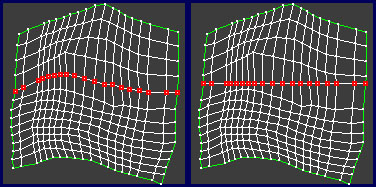
Left: Initial vertex selection
Right: After Align Horizontally
At the Edge level, if you press Shift when clicking the button, Align loops through all selected edges and lines up all the edge loops of those edges horizontally. In that case it is enough to select one edge on each edge loop to line up. It can also line up UV seam edge loops.

Left: Initial edge selection
Right: After Align Horizontally In Place with Shift held down
-
-
 Align Vertically
 - Lines up selected vertices or edges vertically. Choose the method from the flyout:
-
 Align Vertically to Pivot Lines up selected sub-objects vertically and moves them horizontally to the pivot position.
Tip: If you align selected polygons to the pivot, they "collapse" because the command applies to their vertices. For best results, align their left and right edge loops separately.
Align Vertically to Pivot Lines up selected sub-objects vertically and moves them horizontally to the pivot position.
Tip: If you align selected polygons to the pivot, they "collapse" because the command applies to their vertices. For best results, align their left and right edge loops separately. -
 Align Vertically in Place Lines up each set of connected, selected vertices and edges (not polygons) vertically and moves them to the average of their horizontal positions.
At the Edge level, if you press Shift when clicking the button, Align loops through all selected edges and lines up all the edge loops of those edges vertically. In that case it is enough to select one edge on each edge loop to line up. It will also line up UV seam edge loops.
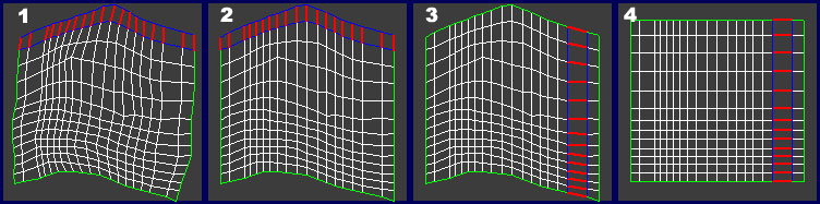
Aligning edges:
1. Initial edge ring selection
2. After using Align Vertically In Place with Shift pressed
3. Initial edge ring selection
4. After using Align Horizontally In Place with Shift pressed
-
-
 Linear Align
 - Lines up selected vertices and edges (but not polygons) between the endpoint vertices, which remain in place.
Left: Initial edge selection
Right: After using Linear Align
-
 Align to Edge
 - Rotates the selected edge to absolute horizontal or vertical, whichever is closest, then selects all remaining edges in the cluster and rotates them the same amount.

Left: Closeup of one edge selected on the top border of the cluster
Right: The edge rotated to horizontal, and the entire cluster rotated the same amount.
-
 Rotate -90 around Pivot
 - Rotates the selection 90 degrees counter-clockwise about the pivot.
-
 Rotate 90 around Pivot
 - Rotates the selection 90 degrees clockwise about the pivot.
-
 Space Horizontally
 - Evenly spaces vertices belonging to multiple, connected, selected horizontal edges, such as an edge loop.
For example, to create a horizontal loop of texture polygons of uniform width, first select the horizontal edge loops above and below the polygons, then click Space Horizontally.

Left: Initial edge-loop selection
Right: After using Space Horizontally; the vertices within each loop are spaced evenly.
Space Horizontally is best used at the Edge level. It also works at the Vertex level, but it converts the vertex selection internally to edges. Thus, to avoid ambiguous results when working at the Vertex level, use it with single loops of selected vertices.
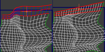
At the Edge level, if you press Shift when clicking the button, Space Horizontally works on the edge loop to which each selected edge belongs. In that case it is enough to select one edge on each edge loop to space. It also applies to UV seam edge loops.
Left: Initial edge ring selection
Right: After using Space Horizontally with Shift pressed to space each edge’s loop
-
 Space Vertically
 - Evenly spaces vertices belonging to multiple, connected, selected vertical edges, such as an edge loop.
For example, to create a vertical loop of texture polygons of uniform height, first select the vertical edge loops on the polygons' left and right sides, then click Space Vertically.
Space Vertically is best used at the Edge level. It also works at the Vertex level, but it converts the vertex selection internally to edges. Thus, to avoid ambiguous results when working at the Vertex level, use it with single loops of selected vertices.
At the Edge level, if you press Shift when clicking the button, Space Vertically works on the edge loop to which each selected edge belongs. In that case it is enough to select one edge on each edge loop to space. It also applies to UV seam edge loops.
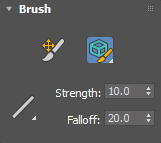
Brush
Use the Brush tool to tweak specific texture coordinates to eliminate or minimize distortion in the map.
-
 UV Paint Movement
 - Moves vertices within a circular brush area with soft selection options.
Tip: Hold Alt to temporarily switch to the Relax brush.
-
 Relax By Polygon Angles
 - Relaxes the selected areas by separate polygon angles. See the Relax Tool dialog for more information.
-
 Relax By Edge Angles
 - Relaxes the selected areas by edge angles. See the Relax Tool dialog for more information.
-
 Relax By Centers
 - Relaxes the selected areas by centers. See the Relax Tool dialog for more information.
-
 Soft Selection Linear Falloff
 - Sets the fallout method to Linear for automatic selections outside of the brush area.
-
Soft Selection Smooth Falloff
- Sets the fallout method to Smooth for automatic selections outside of the brush area.
-
Soft Selection Slow Out Falloff
- Sets the fallout method to Slow Out for automatic selections outside of the brush area.
-
Soft Selection Fast Out Falloff
- Sets the fallout to Fast Out for automatic selections outside of the brush area.
- Strength
- Sets the size of the brush, showing the area as a solid circle.
- Falloff
- Sets the fallout size of the brush, showing the area as a dashed circle.
Reshape Elements rollout

-
 Straighten Selection
 - Rotates the sides of each selected polygon to absolute vertical or horizontal, whichever is closer. The result is a rectangular grid. Applies only to selected texture polygons.
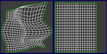
Left: Initial layout
Right: After selecting all polygons, applying Straighten Selection, and deselecting the polygons
Tip: Straighten Selection works best with grid-like polygon layouts, as opposed to radial layouts. -
 Relax Until Flat
 - Changes the apparent surface tension in a selection of texture vertices by moving vertices closer to, or away from, their neighbors, until all polygons are of an equivalent size. Available at all sub-object levels, and, if no sub-objects are selected, applies to all sub-objects.
Relaxing texture vertices can make them more evenly spaced, resulting in easier texture mapping.
-
 Relax: Custom
 - Relaxes the texture vertices using the current settings (see following).
-
 Relax Settings
 - Available from the Relax: Custom flyout. Opens the Relax Tool dialog.
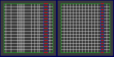
Stitch rollout
Most UV vertices and edges on cluster seams (that is, on the outer edge of a cluster) have
shared sub-objects on other cluster seams. Both represent the same sub-object in the object mesh, but are represented twice or more in the UV mapping because of the subdivision into clusters. Use the Stitch tools to connect selected sub-objects on a cluster seam to their shared sub-objects on another cluster's seam. To see shared sub-objects in the editor window (highlighted in blue by default), turn on Display menu  Show Shared Sub-Objects, or Unwrap Options dialog
Show Shared Subs. You can also use the Show Shared Subs setting to change the color of highlighted shared sub-objects. Also, with
Show Vertex Connections on at the Vertex level, you can see exactly which vertices will be connected to which.
Show Shared Sub-Objects, or Unwrap Options dialog
Show Shared Subs. You can also use the Show Shared Subs setting to change the color of highlighted shared sub-objects. Also, with
Show Vertex Connections on at the Vertex level, you can see exactly which vertices will be connected to which.
Although Stitch works only at the vertex and edge levels, it is available at all sub-object levels, and applies to all seam-based vertices and edges associated with the selected sub-objects. If only one UV vertex is selected and it has more than one corresponding UV vertex, it will be stitched to the closest one. In all other cases Stitch finds the best match, if the match is unselected, or stitches to the selected match.

-
 Stitch to Target
 - Moves the selected sub-objects to the shared sub-objects.
-
 Stitch to Average
 - Moves both sets of sub-objects to the average positions.
-
 Stitch to Source
 - Moves the shared sub-objects to the selected sub-objects.
-
 Stitch: Custom
 - Connects sub-objects based on the current
Stitch Tool dialog settings (see following).
This tool is also available as Stitch Selected on the editor Tools menu.
-
 Stitch Settings
 - Available from the Stitch: Custom flyout. Opens the Stitch Tool dialog.

1. Texture vertices before stitching
2. Stitch to Source
3. Stitch to Average
4. Stitch to Target
Explode rollout
Use the tools in the first row of this rollout for breaking up texture coordinates into separate clusters. The Flatten tools work on selected texture polygons, or if no polygons are selected, on all polygons.
-
 Break
Break - Applies to the current selection; works differently in the three sub-object modes. At the Vertex sub-object level, Break replaces each shared vertex with two vertices. With edges, Break requires at least two contiguous edges to be selected, and separates each edge into two. With polygons, Break splits the selection off from the rest of the mesh into a new element.
-
 Flatten by Polygon Angle
 - Breaks up the texture polygons using the following settings:
- Polygon Angle Threshold=60.0
- Spacing=0.02
- Normalize Clusters=on
- Rotate Clusters=on
- Fill Holes=off
- By Material IDs=off
For explanations of the settings, see Flatten Mapping Dialog.
-
 Flatten by Smoothing Group
 - Breaks up the texture polygons using their
smoothing group IDs.
When flattening by smoothing group, in order to form a separate cluster, a group of polygons must be fully enclosed by hard edges; that is, polygons that do not share any smoothing group IDs with their neighbors. If some polygons have multiple smoothing group IDs, it's possible that the texture coordinates would not be able to be split into separate clusters.
-
 Flatten by Material ID
 - Breaks up the texture polygons into clusters using only Material IDs. Thus it ensures that no cluster contains more than one material ID after flattening.
-
 Flatten: Custom
 - Breaks up the texture polygons using the current Flatten Mapping dialog settings.
-
 Flatten Settings (on Flatten: Custom flyout)
 - Opens the Flatten Mapping dialog for specifying Flatten: Custom parameters.
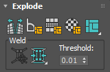
Weld group
With the exception of Target Weld, the Weld commands here combine edges on different clusters at the average of their positions.
-
 Target Weld
 - Combines a pair of vertices or edges into a single sub-object. Available only at the Vertex and Edge sub-object levels.
Turn on Target Weld, and then drag one vertex to another vertex, or one edge to another edge. As you drag, the cursor changes in appearance to cross hairs when it's over a valid sub-object. While this command is active, you can continue welding sub-objects, and change the sub-object level. To exit Target Weld mode, right-click in the editor window.
- Weld Selected flyout
- Provides three different methods for welding selected UVW sub-objects.
Note: Weld Selected Subobject and Weld All Selected Seams work alike in combining shared vertices and edges of selected sub-objects; the difference is that Weld Selected Subobject works only within the specified Threshold distance, while Weld All Selected Seams works at any distance.
Also, in both cases, each pair of sub-objects containing the shared vertices or edges must be selected. With Weld Any Match With Selected, only one of each pair need be selected.
-
 Weld Selected Subobject Combines any shared vertices and edges of selected sub-objects within the current Threshold distance (see following).
-
 Weld All Selected Seams Combines any shared vertices and edges of all selected sub-objects; the Threshold setting does not apply.
-
 Weld Any Match with Selected Combines a selected seam with its counterpart on another cluster without having to select the counterpart edges first.
-
- Threshold
-
Sets the weld threshold: the radius within which welding using Weld Selected and Weld Selected Subobject (see preceding) take effect. The value uses UV-space distance. Default=0.01. Range=0 to 10.
Peel rollout
The Peel tools incorporate the Unfold3D method of unwrapping texture coordinates for an easy and intuitive workflow in flattening complex surfaces. The Unfold3D algorithm now serves as the default rollout for the Peel tools, while providing you with the option to revert to the previous LSCM (Least Square Conformal Maps) method through a drop-down menu in the top left corner of the rollout.
The new rollout includes tools for detaching and packing (avoid overlap) the UVs, along with the Pin aspect of the Peel feature.
A new progress bar also shows Unfold3D's processing status.
- When using the Peel Mode tools, Unfold3D will add pins as needed internally. There's no functionality to manually set pins.
- When in Peel Mode - edge component, there might be a delay in splitting an edge in Unfold3D depending upon the complexity of the solution. A workaround is to use the seam tools to define an edge seam before going into Peel Mode.
- Unfold3D will always succeed in generating its algorithm even if the results may be undesirable.
- Bad existing UV data, such as non-manifold geometry and bow ties, will attempt to be corrected automatically before being processed by Unfold3D. If this correction is unable to resolve the issues, it may result in stretched or triangulated UV coordinates. If this occurs, we recommend that you regenerate the UV data or utilize LSCM.
Additional Algorithm Notes:
- When using Peel Mode in LSCM, pinned vertices are held in place while the rest of the vertices will move.
- When in Peel Mode, the UVs will change their display color to denote this.
- In LSCM, pins can be moved to adjust the shape and size of the UV islands.
- When Peel Mode is active in LSCM, if you select edge mode, the algorithm will automatically cut the UVs to separate the islands. If in vertex mode, selecting a vertex without a pin will add a pin, and you can move it.

- Unfold3D has less distortion. It's the recommended algorithm to use when unwrapping UVs and will give superior results with organic and rounded objects.
- Unfold3D does not use pins.
- The UVs will not change their display color when in Peel Mode.
- When Peel Mode is active in Unfold3D, and you're in edge mode, selecting the edges on the mesh will automatically cut the UVs on the selected edges. When that happens, Unfold3D will re-peel your UVs.

The Peel tools are available in every sub-object mode. If there's a selection in the active mode, it will only peel the selection. If nothing is selected, then all UV coordinates are peeled.
For a brief demonstration of how to use the Peel tools, see this procedure.
-
 Quick Peel
 - Performs a "best-guess" Peel operation on all vertices (except pinned ones) that belong to the selected texture polygons. To do so, Quick Peel distributes the vertices evenly based on their average locations while trying to maintain existing polygon shapes. When Detach is on (see preceding), Quick Peel also separates the peeled cluster from the other texture coordinates. Unselected faces are not affected.
Quick Peel is suitable for simple texture-mapping applications, but for better control, use Peel Mode instead (see following).
Tip: In some cases, repeated applications of Quick Peel can improve the results. -
 Peel Mode
 - Applies a Quick Peel (see preceding) and then stays active so you can adjust the layout of the texture coordinates interactively. You do so by dragging sub-objects in the Edit UVWs dialog window, which redistributes all vertices in the cluster evenly around any pinned vertices. Unselected faces are not affected. To exit Peel Mode, click this button again.
While Peel Mode is active, peeled polygons use distinctive coloring, which makes it easier to see which part of the texture coordinates you're peeling. The color is violet by default; to adjust the color, change the Peel Color setting.
Activating Peel Mode automatically switches to the Vertex sub-object level, but you can use Peel Mode at any sub-object level. When Detach is on (see preceding), Peel Mode also separates the peeled cluster from the other texture coordinates.
While Peel Mode is active, you can create seams with the Edit Seams and Point-to-Point Seams tools and they automatically "peel" off as you go. Alternatively, in the editor, select some edges and use the Break tool to split the edges and automatically re-peel the cluster.
When Auto-Pin Moved Vertices is on (the default), moving a sub-object in Peel mode pins (locks) all vertices belonging to the sub-object.
-
 Reset Peel
 - Merges existing map seams of the polygon selection, converts Peel seams to new map seams, and then Peels the resulting clusters. The borders of the selection are separated from the other clusters and become new map seams.
Use Reset Peel to reconnect map seams on previously mapped geometry, or to quickly break off and Peel a selection.
- Detach
- When on, using Quick Peel or Peel Mode (see following) separates selected polygons from the rest of the texture coordinates automatically. When off, the peeled polygons remain attached to the rest. Default=on.
- Avoid Overlap
- When enabled, selected elements will not touch each other and will also expand to fit inside of the boundary box. When disabled, the selected elements will touch each other and will not move from their original space.
Pins group
When a vertex is pinned, it is held still when you move other vertices in Peel Mode (see preceding). By default, Auto-Pin Moved Vertices is on, so that moving a sub-object with Peel Mode active subsequently pins its vertices.
A pinned vertex is indicated visually with a small blue square outline.
-
 Pin Selected
 - Pins all selected vertices. Available at the Vertex level only.
-
 Unpin Selected
 - Unlocks the positions of selected, pinned vertices so they can then move as part of the Peel Mode process. Available at the Vertex level only.
Note: At least two vertices must always be pinned in Peel mode. If a cluster contains only two pinned vertices, before you can unpin them you must first pin others.
-
 Auto-Pin Moved Vertices
 - When on, moving a sub-object or cluster with Peel Mode active subsequently pins its vertices. When off, you can move only pinned vertices in Peel mode.
-
 Select Pinned Verts
 - When on, you can select only pinned vertices. No other operation is available in this mode. One use is to apply Unpin Selected after selecting vertices in this mode. Available at the Vertex level only.
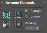
Arrange Elements rollout
Use these tools to arrange elements automatically in various ways. Packing is useful for adjusting the layout so that clusters don't overlap.
The Pack tools apply only to selected clusters when one or more sub-objects are selected, or to all clusters when nothing is selected.
-
 Pack: Custom
 - Distributes texture-coordinate clusters through the texture space using parameters you specify with Pack Settings (see following). This is useful if you have several overlapping clusters and wish to separate them.
Pack: Custom respects the Rescale Priority value (see following) when Rescale Clusters is on.
-
 Pack Settings (from Pack: Custom drop-down)
 - Opens the Pack dialog for specifying Pack: Custom parameters.
-
 Rescale Elements
 - Automatically scales all clusters, in place, in proportion to each other.
Rescale Elements respects the Rescale Priority value (see following) whether or not the Rescale switch is on. When groups are present, it always applies to the group members plus any selection (or all clusters if nothing is selected). If no groups are present, Rescale Elements applies only to selected clusters when one or more sub-objects are selected, or to all clusters when nothing is selected.
-
 Pack Together
 - Moves clusters as closely as possible into the 0-1 UV space (blue square) without normalizing (see Pack Normalize), while respecting the Rescale, Rotate, and Padding settings (see following).
Pack Together respects the Rescale Priority value (see following) when groups are present and the Rescale switch is on.
-
 Pack Normalize
 - The same as Pack Together but automatically scales all clusters uniformly to fit them into the 0-1 UV space (blue square), known as "normalization," while respecting the Rescale, Rotate, and Padding settings (see following).
Pack Normalize respects the Rescale Priority value (see following) when groups are present and the Rescale switch is on.
- Rescale
- When on, and you use Pack Together or Pack Normalize, scales individual clusters so that texture element sizes are uniform.
- Rotate
- When on, and you use Pack Together or Pack Normalize, rotates individual clusters for the most efficient use of space.
Note: In some cases Pack can rotate clusters by 90 degrees even if Rotate or Rotate Clusters (for Pack: Custom) is off.
- Padding
- The spacing between neighboring elements after packing. For best results, use a relatively low value.
Element Properties rollout
Grouping in the Unwrap UVW modifier lets you specify that certain texture clusters should stay together during Pack operations (see preceding). You can also specify relative rescaling for grouped clusters.

- Rescale Priority
- When you use Arrange Elements rollout tools (see preceding), the Rescale Priority value enables relative scaling of clusters (see Arrange Elements rollout, preceding). Range=0.0 to 1.0. Default=1.0.
Rescale Priority applies to these tools under the specified conditions:
- Pack Custom with Rescale Clusters on
- Rescale Elements
- Pack Together with the Rescale option on
- Pack Normalize with the Rescale option on
Note: If you set the value from the keyboard, be sure to press Tab or Enter after entering the value.To use Rescale Priority, first group one or more clusters (see Group Selected, following), then set the value. Then, when you use an operation that involves rescaling, the Rescale Priority value is applied to this group as a multiplier.
For example, say you group some clusters, and then select a polygon belonging to one of the clusters and set Rescale Priority to 0.5. Then you apply Pack Together or Pack Normalize to all clusters, with the Rescale option enabled. The result is that the clusters belonging to the group are half the size that they would be otherwise. (Non-grouped clusters always use a scaling factor of 1.0, or 100%.)
Groups group
The Groups functions are available at the Polygon sub-object level only. Using Pack Together or Pack Normalize on grouped clusters retains the original spatial relationship of the members of each group, and optionally applies scaling based on the Rescale Priority value for a group and the state of the Rescale option.
For example, if two or more clusters are superimposed because they represent different parts of the geometry that use the same part of the texture map, you could keep them from separating during Pack procedures by selecting them all and then clicking Group Selected.
-
 Group Selected
 - Adds clusters to a new group. Select at least one polygon in each of one or more different clusters and then click Group Selected. You can create any number of groups.
After you create a group, you can, in effect, select the group by selecting any polygon in the group. Doing so enables two features:
- The group number appears at the bottom of the rollout.
- The Rescale Priority setting shows the current value. If you change the value, it applies to all members of the group.
-
 Ungroup Selected
 - Deletes an existing group. Select at least polygon in a grouped cluster and click Ungroup Selected to remove all clusters from the group and eliminate the group.
-
 Select Group
 - Selects all clusters belonging to a group. Select at least one polygon in the group and then click Select Group to select the clusters.
If you use Select Group with multiple groups (that is, multiple polygons selected in different groups), only one group is selected. Which group gets selected is unpredictable.
- No groups selected / Selected groups # # ...
- This read-only field reads "No groups selected" when no polygons are selected that belong to any groups. If one or more polygons that belong to grouped clusters are selected, the field reads "Selected groups # # ..." where each # shows the group number or numbers selected.