Callout tools allow you to define portions of the building model as details, sections, and elevations. These portions are placed in model space views created for the callout.
A model space view is a portion of a view drawing that may be displayed in its own viewport on a layout tab of a drawing. A model space view has its own name, description, display configuration, layer snapshot, drawing scale, layer state, and view direction. Model space views are an evolution of the Named Views concept of AutoCAD, but as opposed to Named Views, model spaces views have a defined boundary.
You can place a model space view containing a detail, section, or elevation in the current view drawing, an existing project view drawing, or a new project view drawing.
The New View Drawing Types
View drawings have been enhanced for AutoCAD Architecture 2022 toolset. In addition to the existing general view drawings, users may now access some specialized drawing types designed for saving details, sections, and elevations in a project. All of these view types are organized in the Project Navigator.
These are the types of view drawings in the Drawing Management feature:
- General view drawings: A general view drawing contains referenced constructs from the project, representing a specific view on the building model. General view drawings are based on the general view template defined in the project settings.
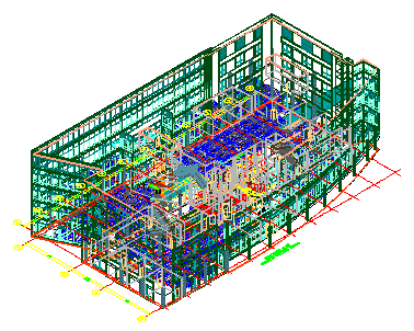
3D view of entire building
- Detail view drawings: A detail view drawing can contain one or more model space views that show a defined portion of the building model. This could be a detail or an enlarged part of a plan. You can specify the level of detail with the help of the display configuration and the 2D Section/elevation style. A model space view containing a detail can be created with a callout. Detail view drawings are based on the detail view template defined in the project settings.
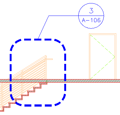
Detail view in callout
- Section/Elevation view drawings: A section/elevation view drawing can contain one or more model space views that show a section/elevation of the building model. A model space view containing a section or elevation can be created with a callout. Specific callout tools have been added to make the creation of four-way exterior and interior elevations easier and better. Section/elevation view drawings are based on the section/elevation view template defined in the project settings.
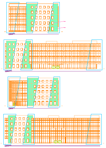
4 model space exterior elevations
Using Fields in Callout Tools
Fields enhance the documentation capabilities within a drawing file. A field is updatable text that is set up to display data that may change during the life cycle of the drawing. When the field is updated, the latest value of the field is displayed. Fields can be inserted into attribute definitions and can be used to create callout tools.
Callouts and Projects
Callouts and their referenced model space views are closely linked to projects in the Drawing Management feature. Although you can use callouts to some degree outside a project, to use them optimally, you need to be working within a project.