You can use callout tools to create section views, elevation views, and detail views that are referenced to a callout. Depending on the view type you want to create, you need to set different options in the callout tool.
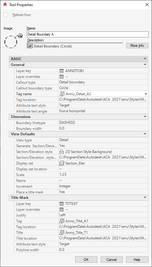
Properties of a detail callout
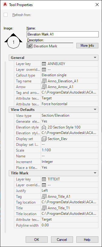
Properties of an elevation callout
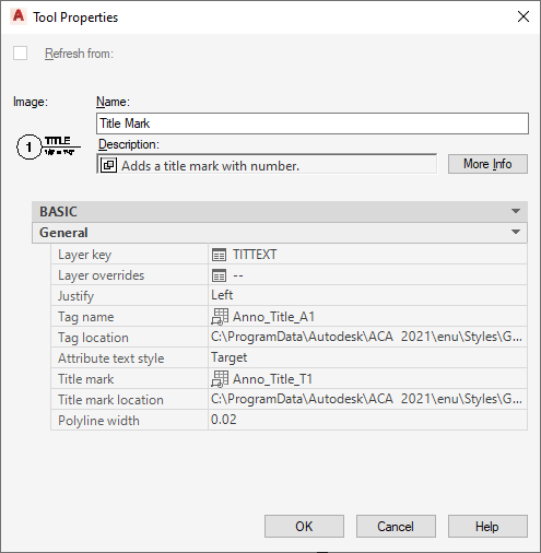
Properties of a title mark tool
The following table lists the properties you can set for the individual tool types.
| Property | Tool Type | Description |
|---|---|---|
| General Category | ||
| Layer Key | General (all callout types) | Here, you specify the layer key in which the callout symbol should be inserted. |
| Layer Overrides | General | If necessary, you can specify a layer key override for the callout symbol here. |
| Callout type | General | Here, you define the type of callout tool you want to insert. You can choose between these types:
|
| Callout boundary type | Detail Boundary | You can choose the shape of the detail boundary. Available options are circular, rectangular, and freeform. |
| Four way elevation type | Elevation Four Way | You can select the type of four-way elevation the tool should create. Available options are interior and exterior elevations. Note: For an interior elevation, you can select spaces as the elevation region.
|
| Tag name | General | Here, you define the block that is used as the callout tag. |
| Tag and arrow location | General | Defines the location of the available callout symbol tags, and, if applicable, the location of the available tag arrows. |
| Arrow | Section/ Elevation | Define the block for the section/elevation mark arrow. |
| Attribute text style | General | Here you select if the text style for attributes in the callout should be the text style of the callout tag (Content) or the current text style of the drawing (Target). |
| Attribute text angle | General | Here, you select the text angle of the attribute text. You can choose to insert the attribute text at the same angle as the callout symbol (As Inserted), horizontal in the drawing (Horizontal), or to be read from the right side (Right Reading). |
| Dimensions Category | ||
| Corner Radius | Detail Boundary | Defines the corner radius of rectangular and freeform detail boundaries. |
| Boundary linetype | Detail Boundary | Defines the linetype of the detail boundary. |
| Boundary width | Detail Boundary | Defines the line width of the boundary lines. |
| View Defaults Category | ||
| View Type | General | This setting determines the type of view generated by the callout tool. You can choose between the following:
|
| Generate Section/Elevation | General | Here, you can choose if the tool should create a 2D section elevation. |
| Section/Elevation style | General | If you have selected to generate a 2D section/elevation from the tool, you need to set a 2D section/elevation style. |
| Section/Elevation style location | General | Sets the drawing or template file from in which the available 2D section/elevation styles reside. |
| Display set | General | If you have selected to generate a 2D section/elevation from the tool, you need to set a display set for the 2D section/elevation here. |
| Display set location | General | Sets the drawing or template file from in which the available display sets reside. |
| Scale | General | In this setting, you define the scale of the model space view generated from the tool, as well as the scale of sheet views generated from the model space view. Note: You can override the scale set in the tool during insertion of the callout in the drawing.
|
| Name | General | Sets a default name for model space views that are created by this tool. You can override the name set in the tool when inserting a callout in the drawing. |
| Increment | General | Sets a default incrementing method for naming multiple model space views created with this callout tool. Available options are Integer and Character. |
| Place a title mark | General | Here, you can select if a title mark should be attached to model space views created with this tool. |
| Title mark Category | ||
| Layer Key | General | By default, a title mark that is associated to a callout tool is inserted on the same layer as the model space view generated. You can however define a different layer for the title mark by selecting a different layer key here. |
| Layer Overrides | General | If necessary, you can specify a layer key override for the title mark here. |
| Justify | General | This setting specifies the justification of the title mark in relation to the title mark line. Available options are Left and Right. |
| Tag | General | In this list, you select the block used for the title mark symbol. |
| Tag location | General | Sets the drawing or template file from in which the available blocks reside. |
| Title | General | Here, you define the title symbol. |
| Title location | General | Sets the drawing or template file from in which the available title symbols reside. |
| Attribute Text Style | General | Here you select if the text style for attributes in the title should be the text style of the title tag (Content) or the current text style of the drawing (Target). |
| Polyline width | General | This setting specifies the width of the polyline separator. The value is measured in plotting units and scaled appropriately based on the current annotation scale. |