A display configuration is a collection of display sets assigned to view directions.
Display Configurations, Viewports, and Templates
A display configuration typically is created for a specific design task or drawing type. To use a display configuration, you assign it to a viewport. Drawings based on templates provided with AutoCAD Architecture 2022 toolset contain layout tabs with viewports to which appropriate display configurations are assigned. You can use the configuration assigned to a viewport, assign a different one, or customize the configuration.
Display Sets Assigned to View Directions
You can identify the display set assigned to each view direction using the Display Manager. The Display Manager is a utility for managing elements of the display system. The following illustration shows a drawing with two display configurations, Medium Detail and Standard.
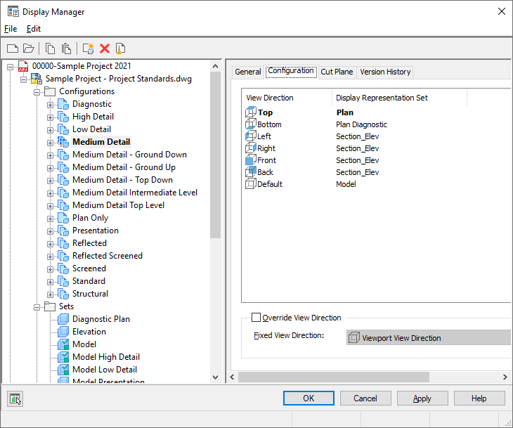
Sample display configurations in the Display Manager
In the Display Manager, the active viewport in the drawing (in bold type) is assigned the Medium Detail display configuration. In the left pane, the display sets used are listed below the configuration name. An icon next to each display set indicates the view direction to which the display set is applied. The Configuration tab in the right pane shows the view direction to which each display set is mapped. In this example, the current view direction in the drawing is Top, which uses the Plan display set. Objects in the active viewport are shown using the display representations in the Plan display set.
If the view direction in the active viewport is changed to Front, the objects are shown using the display representations in the Section_Elev display set. This is also true when the view direction in the active viewport is changed to Right, Left, or Back.
The display set assigned to the Default view direction is used when any view direction other than the six orthogonal views is selected, or when a view direction is not assigned a display set. If the view direction of the active viewport is changed to Bottom, objects are shown using the display set assigned to the Default view direction—the Model display set.
Displaying Objects in a Viewport
The display configuration, the current viewport, and the object interact in the following manner to determine what is shown in a viewport:
- The active viewport has a current view direction and a current display configuration. For example, the view direction is Top, and the display configuration is Medium Detail.
- The display configuration has one or more display sets and uses the display set that is assigned to the current view direction. For example, in the Medium Detail display configuration, the Plan display set is assigned to the Top view.
- The display set has associated display representations and it selects the representation(s) associated with the object that needs to be shown. For example, in the Plan display set, doors, windows, and walls use their Plan display representations.
- The object is shown in the active viewport using the appropriate display representation(s) and display properties.
Examples of View Directions That Use Different Display Sets
A display configuration assigns display sets to specific view directions. When a view direction is selected, the display representations in the display set determine how each object is displayed in the viewport.
For example, the following illustration shows a viewport assigned the Plot display configuration and the Top view direction. In this illustration, the objects are shown with a Plan display representation.
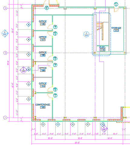
Objects from Top view using a display set for plan views
If the Front view direction is selected in this viewport, the same objects are displayed with an Elevation display representation.
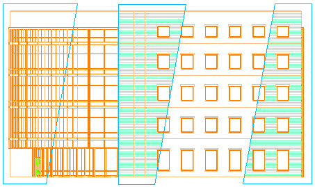
Objects from Front view using a display set for elevation views
If the SW Isometric view direction is selected, the same objects are displayed with a three-dimensional (3D) representation.
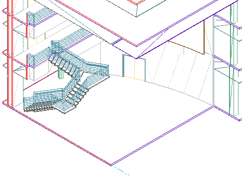
Objects from SW isometric view using a display set for model views
Default Display Configuration
The display configurations in a drawing depend on the template used to create the drawing. A drawing that is not created from a template contains the Standard display configuration, which includes the Plan and Model display sets.