Delete components
The Delete Component command lets you remove the selected component. The broken wires are repaired and any resulting instances of multiple wire numbers now assigned to a single wire network are reconciled. In the case of a child contact, AutoCAD Electrical toolset looks for its parent on the current drawing and removes the deleted contact from the parent's cross-reference annotation (if the parent is on some other drawing then a separate run of the Cross-reference command may be required on the drawing set). If you erase a parent schematic component you will have the option to search for related child components, surf to them, and optionally delete them.
For a child contact, Delete Component updates the cross-reference on the parent. If you erase a parent schematic component, you have the option to search for related components and delete them.

Scoot components/wire segments
Scoot quickly repositions components and wire segments. Click a component to slide just that component along its connected wires. Wires remain connected and existing wire numbers center themselves. To scoot a ladder rung, including all its components and wire numbers, click any wire segment.
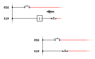
The component’s movement will be constrained along the wire segment. To scoot a ladder rung, including all its components and wire numbers, select directly on any wire segment that makes up the rung. Scoot works on wire numbers, components, terminals, PLC I\O modules, jogs in dashed link lines, signal arrows, wires, and wires with wire-crossing loops.
Align components/wire numbers
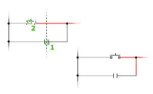
The Align Components command aligns the selected component with a master component that you select.
Select the components individually or with a window. Align adjusts all connected wires, and recenters wire numbers. Align vertically or horizontally by flipping the command with a V or H character followed by a [space] entered on the command line.
Move components
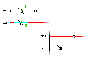
A Move Component operation breaks and reconnects any underlying wires, and inserts a rotated version of the symbol, if necessary. It repairs broken wires and removes unnecessary wire numbers left in the position the component vacated.
Stretch PLC Modules, Components, Blocks
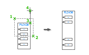
The Stretch PLC Module command is intended to allow you to add space between I/O points on a PLC module, but can be used on any block. Let's say you have a PLC module and you need to add a couple components in parallel on a particular rung and you did not leave enough room between the I/O points. You could erase everything and rebuild the module and then reinsert the components, redo the wiring, etc. or you could use the Stretch PLC Module command.
Maintains all the original block information, including attributes.
Split PLC modules
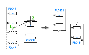
The Split PLC Module command is especially handy for splitting PLC modules once they have been built or inserted. Maybe you need to move the last few I/O terminal points to another ladder to make room for some other devices.
You specify:
- Origin point for the new block
- Break type
- Layer for the child block
- Whether to reposition the child block
Reverse/Flip Components
Available when a component has only two wire connections. Specify to reverse or flip only the graphics, or include component attributes.
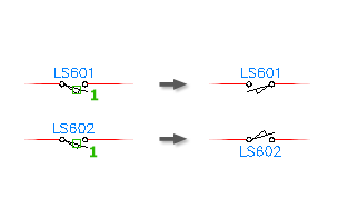
Swap Contact States
The program looks at the selected contact, reads its block name, and checks the fifth character for either 1 or 2. It looks for a matching block name with the opposite 1 or 2, and swaps this block for the existing block.
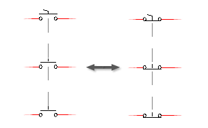
Existing attribute text is preserved on the flipped contact. If the maximum contact counts are carried by the parent symbol, the maximum counts are checked so that they are not exceeded by the flip.